The Complete DAF Process Flow at a Glance
A dissolved air flotation process flow diagram shows industrial wastewater entering screening or equalization as applicable, followed by chemical conditioning, mixing, and flocculation. The conditioned stream enters a flotation tank, where fine bubbles carry suspended solids, oils, grease, biological solids, and flocs to the surface. A skimmer removes the float, clarified water leaves below the float layer, and sludge goes to handling or dewatering. Part of the clarified water is recycled through an air-saturation vessel and returned to the tank; this is not the product-water outlet. DAF removes suspended or floatable material, not dissolved salts or very small molecules, so biological, filtration, activated-carbon, or reverse-osmosis treatment may still be required.
Use the diagram below to separate the three principal flows. The main wastewater path runs from influent through conditioning and flotation to the clarified-water outlet. The recycle path runs from clarified water through the recycle pump, air-saturation vessel, and return connection. The removed-float path runs from the surface skimmer to sludge handling. A complete review of a proposed HydropureWater DAF system should make those three paths explicit.
| Flow path | Diagram sequence | Engineering meaning |
|---|---|---|
| Main wastewater path | Industrial wastewater influent → screening or equalization, as applicable → chemical conditioning and mixing → flocculation → DAF flotation tank → clarified-water outlet | Suspended and floatable contaminants are separated before the clarified water enters its intended destination. |
| Recycle and saturation path | Clarified-water takeoff → recycle pump → pressurized air-saturation vessel → return to flotation tank | Compressed air dissolves in pressurized water and forms fine bubbles when pressure falls in the flotation tank. |
| Removed-float path | Surface float → scraper or skimmer → sludge handling, thickening, dewatering, treatment, or disposal | The concentrated float is a separate waste stream and must have a defined route. |
| Optional downstream path | Clarified water → biological treatment, filtration, activated carbon, reverse osmosis, discharge, or reuse | The correct destination depends on dissolved pollutants, outlet objectives, and applicable requirements. |
DAF is relevant when gravity separation is unreliable, particularly for oils, grease, biological solids, and light or slow-settling suspended contaminants. Clear Water Industries identifies these materials as common DAF targets and describes the process as separating suspended matter by floating it to the surface rather than settling it to the bottom.
How Each Stage of the Flow Diagram Works
DAF depends on preparing the wastewater so that contaminants can attach to bubbles and separate cleanly from the water. The operating sequence begins with characterising the influent, not merely estimating its average flow.
- Influent preparation: Establish flow variability, suspended material, oils and grease, pH, and conditioning needs. Screening may protect the treatment train from large debris, while equalization may be required where flow or pollutant loading varies materially.
- Chemical conditioning and mixing: Coagulants or polymers may destabilise colloidal particles and form larger flocs that attach more readily to bubbles. Clear Water Industries identifies ferric chloride and aluminium sulfate as common coagulant examples. An automatic chemical dosing system should be tied to the selected control strategy rather than treated as an isolated accessory.
- Flocculation: The conditioned wastewater enters a flocculation zone where solids agglomerate. Stable colloidal particles may not attach efficiently to bubbles without this preparation.
- Flotation: Fine bubbles attach to suspended solids, oils, grease, and conditioned flocs. Bubble attachment increases effective buoyancy and carries the material toward the surface.
- Surface separation: A surface scraper or skimming device removes the concentrated float and directs it to sludge handling, thickening, dewatering, additional treatment, testing, or disposal.
- Clarified-water withdrawal: Treated water leaves from below the floating-solids layer. It may proceed to discharge, biological treatment, filtration, or another stage, subject to the intended use and applicable requirements.
DAF primarily removes suspended or floatable contaminants. It does not remove all dissolved contaminants, salts, or very small molecules, so downstream biological, filtration, activated-carbon, or reverse-osmosis treatment may still be required. The 2026 DAF unit selection and cost framework provides a useful basis for connecting the outlet to the complete treatment train.
The skimmer is not a minor accessory. If the float is not removed consistently, it can accumulate in the tank and interfere with separation. Likewise, the sludge route must be designed before procurement because the removed float can require further handling. Clear Water Industries notes that float composition determines whether thickening, dewatering, testing, treatment, and disposal are required.
Trace the Recycle and Pressurization Loop

The recycle loop is the mechanism that creates flotation capacity: clarified water is pressurized, loaded with compressed air, and returned to the tank at reduced pressure so dissolved air becomes fine bubbles.
- The recycle pump takes a defined portion of clarified effluent from the flotation tank.
- The pressurized water passes through the air-saturation vessel, where compressed air enters and dissolves under pressure.
- The saturated recycle returns to the flotation tank.
- As pressure falls, the dissolved air forms fine bubbles that can attach to flocs, oils, grease, and suspended particles.
Saturation pressure and recirculation ratio are separate design variables. The first affects the available dissolved-air condition; the second determines how much clarified water participates in the recycle circuit. Neither should be copied from another wastewater application without representative testing and equipment design.
| Scoped study result | With CaCl₂ | Without salt |
|---|---|---|
| Saturation pressure | 5 bar | Similar pressure |
| Recirculation ratio | 80% | Similar ratio |
| Flotation time | 30 minutes | 36 minutes |
These values come from the ACS Omega study published on 2025-10-30, “Optimization of Dissolved Air Flotation in the Treatment of Coffee Processing Wastewater Using Calcium Chloride.” They apply specifically to that coffee-processing wastewater and its coagulation-flocculation-DAF configuration. They are not universal design defaults because wastewater composition, chemical conditioning, treatment objective, and equipment arrangement all affect performance.
For operating review, monitor recycle flow, saturation pressure, compressed-air availability, and observed bubble performance. Clear Water Industries identifies recycle pressure and flow stability as operating requirements. A stable-looking pressure reading is not enough if air delivery is poor or the pressure vessel is not transferring air effectively. Troubleshooting should connect the symptom—carryover, poor float, unstable separation—to the relevant pump, vessel, air supply, control point, and chemical condition.
Read the Diagram Like an Engineer
A useful P&ID review links every diagram element to the variables that determine performance. If a block has no design input, control point, or performance indicator, it is still an unresolved assumption.
| Diagram element | Function | Design or operating input | Performance indicator |
|---|---|---|---|
| Influent and equalization | Removes unsuitable material and moderates flow or loading variation where required | Representative wastewater characterization, peak flow, suspended solids, oils and grease, pH | Stable feed condition and no screening or equalization constraint |
| Chemical conditioning | Destabilises colloids and forms floatable flocs | Trial-selected chemical type, dose, mixing, and pH | Low carryover without excessive chemical use or sludge generation |
| Recycle and saturation | Generates fine bubbles for attachment | Recycle flow, pressure, air supply, and saturation arrangement | Stable recycle conditions, reliable air transfer, and consistent bubble formation |
| Flotation tank | Separates conditioned material from water | Hydraulic loading, pH, particle characteristics, flotation residence, and conditioning need | Clarified-water quality and float concentration |
| Surface skimmer | Removes accumulated float from the tank | Scraper travel or operation, drive arrangement, and float depth | Consistent removal without leaving a persistent float layer |
| Sludge route | Transfers removed float to its next destination | Float composition, thickening need, dewatering method, testing, and disposal route | Manageable sludge volume and an approved receiving process |
| Clarified-water outlet | Supplies the next treatment stage or permitted destination | Required outlet quality, downstream process limits, and applicable requirements | Performance against the intended downstream or reuse specification |
Chemical dose should be established from representative wastewater tests. Clear Water Industries states that underdosing can leave suspended matter and cause carryover, while overdosing can increase sludge production and operating costs. For food-processing applications, the DAF selection for food-processing wastewater guide provides application-specific context.
Downstream evaluation should follow the stream. If the float requires dewatering, compare the solids characteristics with a suitable plate and frame filter press. If the clarified water feeds biological treatment or membranes, evaluate the pollutants and solids remaining after DAF rather than assuming that flotation alone satisfies the downstream equipment’s requirements.
Match the Flow Diagram to Your Wastewater and Treatment Train
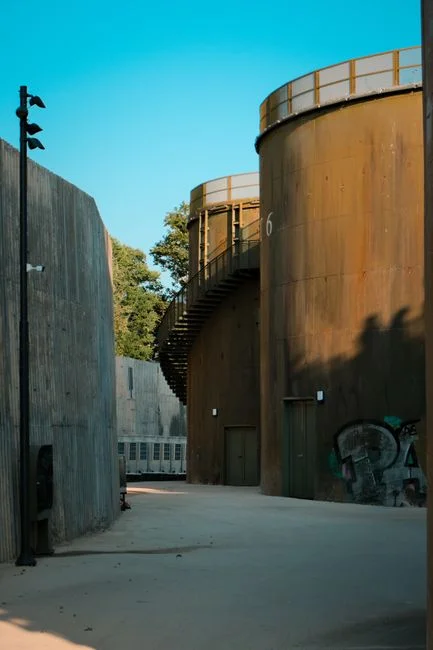
DAF fits a wastewater and treatment train when the target contaminants are suspended, floatable, or chemically convertible into floatable flocs. Application mapping provides an initial screening tool, but representative wastewater testing remains necessary for selection.
| Application | Characteristic material associated with DAF use | Decision focus |
|---|---|---|
| Food and beverage | Fats, oils, grease, food particles, proteins, and suspended solids | Variable composition, chemical demand, float recovery, and downstream biological treatment |
| Pulp and paper | Fibres, fillers, and light suspended solids | Solid recovery objective and downstream clarification |
| Textile | Oils, lint, surfactants, and suspended particles | Emulsified contaminants and conditioning strategy |
| Metalworking | Oils, emulsions, precipitated metals, and process residues | Chemical precipitation or conditioning before flotation |
| Petrochemical | Free and emulsified oils, suspended matter, and process residues | Hydrocarbon separation, fire and safety considerations, and downstream treatment |
| Municipal pretreatment | Algae, biological floc, and light solids | Peak loading, clarification duty, and subsequent treatment capacity |
HydropureWater’s verified product catalog lists DAF systems from 4–300 m³/h across 13 standard models, using micro-bubble technology and automatic skimming. The catalog identifies food processing, pulp and paper, textile, metalworking, petrochemical, and municipal pretreatment applications. This range establishes the available model envelope, not the selected capacity for a particular wastewater.
Compare DAF with conventional settling according to contaminant behaviour. DAF is suited to light, suspended, or floatable material; dense, readily settleable solids may be better handled by clarification. For food-processing wastewater, the DAF and API separator cost comparison can support commercial evaluation, while the DAF versus API separator application guide addresses process fit.
The final selection should be based on representative wastewater tests, peak flow, solids loading, oil-and-grease loading, chemical demand, required outlet quality, available footprint, sludge route, and downstream equipment protection. If dissolved pollutants or stringent reuse requirements dominate, define the downstream biological, filtration, activated-carbon, or reverse-osmosis stages before approving the DAF scope.
From P&ID to Purchase Specification
A generic process picture is insufficient for procurement because it can conceal unresolved sizing, control, and boundary-of-supply assumptions. Require the supplier’s drawing to identify the complete DAF recycle and saturation system, not only the flotation tank.
- Mark every stream and connection: Identify the industrial wastewater influent, clarified-water outlet, recycle takeoff, recycle return, air-saturation equipment, chemical-conditioning points, surface skimmer, sludge outlet, and downstream connection points.
- State the design basis: Require the selected flow basis, recycle arrangement, saturation-pressure basis, air-supply requirements, chemical-conditioning scope, sludge-removal method, controls philosophy, and utility requirements.
- Define abnormal conditions: Ask how the system handles flow fluctuations, chemical overdosing, compressed-air interruption, scraper failure, sludge accumulation, and clarification carryover.
- Separate guarantee from assumption: Identify which parameters are guaranteed, the method used to demonstrate performance, and the wastewater sample or pilot data that informed equipment selection.
- Fix the scope boundaries: State which civil work, chemical equipment, compressors, air receivers, instruments, controls, electrical supply, installation, commissioning, training, and downstream connections are included.
| Specification item | Information to request | Acceptance check |
|---|---|---|
| Design basis | Representative wastewater, peak flow, loads, pH, outlet quality, and treatment objective | Inputs match the buyer’s documented wastewater and duty |
| Drawing | Marked P&ID with main, recycle, air, float, and clarified-water streams | No stream, connection point, or control point is ambiguous |
| Recycle system | Pump, saturation vessel, pressure basis, air-supply demand, controls, and return arrangement | Equipment and utilities are included within the stated scope |
| Conditioning | Chemical type, trial basis, dosing equipment, mixing, and adjustment strategy | Scope and operating responsibility are defined |
| Sludge removal | Scraper mechanism, float outlet, thickening or dewatering interface, sampling, and disposal boundary | The removed float has a complete receiving route |
| Controls and guarantees | Control narrative, alarms, interlocks, test method, guarantees, exclusions, and commissioning criteria | Performance obligations and acceptance tests are explicit |
Where upstream solids screening is required, the rotary mechanical bar screen can be specified as a separate boundary. For brewery wastewater, the brewery spent-yeast DAF sizing guide demonstrates why application-specific inputs must replace copied operating values.
Frequently Asked Questions
What does a dissolved air flotation process flow diagram show?
It shows three principal flows: wastewater moving through conditioning, flocculation, and flotation; clarified water moving through the recycle pump and air-saturation vessel before returning to the tank; and separated float moving to sludge handling. The clarified-water outlet must be distinguished from the recycle return because the recycle stream is reused within the process.
How do I size a DAF system for industrial wastewater?
Start with representative wastewater tests covering peak flow, suspended solids, oils and grease, pH, and chemical demand, then define the required outlet quality and downstream treatment needs. Use the ACS Omega coffee-processing study values—5 bar saturation pressure, 80% recirculation ratio, and 30-minute flotation time with CaCl₂—only as a scoped example from 2025-10-30, not as default design inputs.
How much should a DAF system cost?
A defensible quotation depends on selected capacity, wastewater characteristics, chemical-conditioning requirements, recycle and air-saturation design, controls, skid construction, sludge handling, and downstream scope. Request an itemised quotation with the design basis and exclusions. Without that information, a single price would not represent the actual configuration.
Which questions should I ask a DAF supplier?
Ask where the drawing boundaries begin and end; what flow basis, recycle arrangement, pressure basis, air demand, controls, and sludge outlet are included; which performance parameters are guaranteed; and what sample or pilot data informed the selection. Also require the acceptance-test method, installation requirements, maintenance access, and a written list of exclusions.
Is DAF sufficient for discharge or wastewater reuse?
Not by itself. DAF separates suspended and floatable material but does not remove dissolved salts or very small molecules. The final treatment train must address the remaining pollutants and meet the applicable discharge, reuse, sewer, pretreatment, or permit requirements for the specific site.