
What treatment does a Katsina data center actually need?
A Katsina data center needs separate treatment paths for sanitary sewage, cooling-tower blowdown, industrial process wastewater and stormwater because their flows, chemistry, temperatures, chemicals and final destinations differ. Cooling blowdown should be characterized for flow, temperature, pH, conductivity/TDS, silica, calcium, alkalinity, suspended solids and residual chemicals before equipment is sized. Treatment capacity must come from the approved heat-rejection load, cooling configuration and site water balance, not IT load alone. Final limits depend on the authorized discharge route and current Katsina, state and federal approvals; Lagos and Port Harcourt data provide context, not Katsina site conditions.
The River Ginzo study is useful because it establishes that Katsina has local municipal-wastewater evidence, but it does not define a data-center treatment train. The International Academic and Research Consortium collected municipal sewage samples from River Ginzo in Katsina Metropolis between May and June 2020 and investigated nutrient removal and bioremediation. That work supports the need to characterize local wastewater; it does not establish the composition, flow or permitted destination of a private data center’s cooling blowdown.
Stormwater should be kept out of the sanitary and blowdown treatment hydraulics through a separately managed drainage system. Otherwise, rainfall events can inflate equipment size and introduce uncontrolled contaminants. Likewise, an industrial process stream must not be merged with sanitary sewage or blowdown until its source, chemistry and disposal route are defined.
| Decision area | Required Katsina-specific evidence | Design consequence |
|---|---|---|
| Heat rejection and cooling | Approved heat load, configuration and water balance | Determines evaporation and blowdown flow |
| Sanitary sewage | Occupancy-driven flow and local wastewater characterization | Sets biological treatment and effluent or reuse criteria |
| Cooling blowdown | Seasonal source-water and blowdown analysis | Sets pretreatment, polishing, reuse and discharge requirements |
| Industrial process wastewater | Process inventory, chemical inventory and batch discharge profile | May require segregation or an authorized waste route |
| Stormwater | Drainage design and site runoff assessment | Keeps runoff out of process treatment capacity |
| Approvals | Authorized receiving point and current permit conditions | Sets the final treatment target |
This is a pre-design decision guide. It should be followed by site sampling, receiving-point confirmation, an approved water balance and an engineered process design. The Agege data-center wastewater and cooling blowdown guide provides a useful stream-separation framework, but its site assumptions must not be transferred to Katsina.
Separate the streams before selecting equipment
Four flow diagrams should be developed before any treatment package is priced: sanitary sewage, cooling blowdown, industrial process wastewater and stormwater. Each diagram must identify its source, flow path, treatment stages, residual-waste route and final destination. A combined treatment plant may be considered only after hydraulic and contaminant mass balances demonstrate that the streams can share equipment without compromising biological treatment, membrane protection, reuse quality or permit compliance.
Cooling blowdown is not interchangeable with sewage. It typically contains concentrated dissolved solids, suspended material and residual cooling-water treatment chemicals, and its temperature may differ materially from sanitary wastewater. Sanitary sewage should therefore remain on a biological or municipal-style treatment path unless the wastewater network and final reuse route genuinely require another arrangement. The broader industrial process-wastewater separation framework shows why source-specific segregation must precede equipment selection.
Stormwater should follow a controlled drainage route, with any reuse or discharge subject to the same destination checks as other site water. It should not enter the main process train simply because an underground connection is convenient.
| Flow diagram | Indicative source | Required destination decision | Prohibited assumption |
|---|---|---|---|
| Sanitary sewage | Toilets, kitchens and staff facilities | Approved reuse, sewer or treatment/discharge route | That sewage chemistry resembles cooling blowdown |
| Cooling blowdown | Cooling-tower control loop | Cooling make-up, lower-grade reuse or approved discharge | That direct reuse or discharge is permitted |
| Industrial process wastewater | Specific production, laboratory or treatment processes | Approved reuse, treatment/discharge or hazardous-waste collection | That an unspecified batch stream can enter the main plant |
| Stormwater | Roof and site drainage | Controlled drainage, approved reuse or permitted discharge | That uncontrolled runoff can size the treatment plant |
Unauthorized discharge, reuse without approval, and combination without hydraulic and contaminant mass balances are design exclusions—not options to be resolved after procurement. The destination must be selected first because it determines whether the project needs solids removal, biological treatment, membrane polishing, disinfection or a controlled waste-collection route.
Characterize Katsina source water and cooling blowdown

The Katsina characterization program should analyze the actual cooling configuration—evaporative, hybrid or once-through—because recoverable volume and blowdown concentration depend on how the system operates. Source water and blowdown should be sampled across operating and seasonal conditions, not inferred from one laboratory result or transferred from a coastal city.
For blowdown, the monitoring scope should include flow, temperature, pH, conductivity/TDS, silica, calcium, alkalinity, suspended solids and residual chemicals. The chemical program for corrosion control, scale inhibition, disinfection and microbiological control must be included in the sampling record. A generic “TDS result” does not establish suitability for reuse or discharge.
HydropureWater’s Lagos reference, dated 2026, reports municipal and borehole feed water at 200–600 mg/L TDS and cooling-tower blowdown at 1,200–6,000 mg/L TDS. Those are Lagos benchmarks only: they provide a preliminary testing frame but do not establish Katsina source-water chemistry, blowdown chemistry or permit limits. The 2026 cooling-blowdown treatment engineering guide similarly emphasizes site characterization rather than importing generic capacities.
Metering should reconcile makeup water, blowdown, evaporation and unmeasured losses. Genesis Water Technologies’ 2026 baseline guidance identifies monitoring of makeup, blowdown, evaporation, conductivity, pH and suspended solids as the basis for separating consumption from returned water. Without that reconciliation, a lower discharge flow can be mistaken for lower consumption.
| Parameter | Where to measure | Design use |
|---|---|---|
| Flow | Makeup, blowdown, evaporation estimate and drainage | Hydraulic balance and treatment capacity |
| Temperature and pH | Source water and cooling blowdown | Equalization, material selection and discharge assessment |
| Conductivity/TDS | Source water, circulating water and blowdown | Cycles-of-concentration control and salt balance |
| Silica, calcium and alkalinity | Source water and blowdown | Scaling and make-up reuse assessment |
| Suspended solids and turbidity | Cooling water and treatment stages | DAF, filtration and membrane protection |
| Residual treatment chemicals | Cooling loop and effluent | Disinfection, dechlorination and reuse compatibility |
Seasonal sampling should capture source-water changes, cooling performance and changes in the cooling-water treatment program. Each analytical result should be linked to an operating condition, sample date, flow condition and sample location so that the design can address variability rather than a single favorable sample.
Calculate blowdown and treatment capacity from the water balance
Blowdown capacity should be derived from the approved heat-rejection load and operating water balance, not a generic flow allowance per data-center megawatt. Genesis Water Technologies’ 2026 theoretical relationship is:
Blowdown ratio = 1 ÷ (CoC − 1)
The same source reports a 25% blowdown ratio at 4 cycles of concentration and 20% at 6 cycles. Moving from 4 to 6 CoC therefore reduces blowdown volume by 20%, not 50%. Genesis Water Technologies also warns that biological, scaling and corrosion risks increase above 5–6 CoC without advanced control. The operating target must therefore balance water reduction against the cooling-water chemistry program and asset risk.
For its stated 50 MW heat-load example, Genesis Water Technologies’ 2026 article reports approximately 99,537 kg/h evaporation, about 33,000 kg/h blowdown at 4 CoC and about 19,900 kg/h at 6 CoC, assuming 80% cooling-tower efficiency. These figures are an illustrative source calculation, not a Katsina design case. The actual site heat load and cooling arrangement may be materially different.
Genesis Water Technologies’ 2026 guidance also states that measured blowdown can exceed theoretical calculations by 15–30% because of unmeasured losses and emergency dumps. The final design should preserve an explicit operational allowance based on the site’s metering and dump strategy rather than applying an invented margin.
- Confirm the approved heat-rejection load and cooling configuration.
- Determine evaporation from operating data and the site water balance.
- Select the operating CoC only after reviewing scaling, corrosion and microbiological controls.
- Calculate theoretical blowdown and reconcile it against metered discharge.
- Define operating hours, abnormal dumps, storage and treatment response before selecting capacity.
Equipment sizing then requires measured flow, variability, treatment-stage recovery, operating strategy and the available maintenance response. Where those inputs are unavailable, the correct output is a design hold point—not a provisional capacity claim.
Match each treatment stage to its contaminant and destination
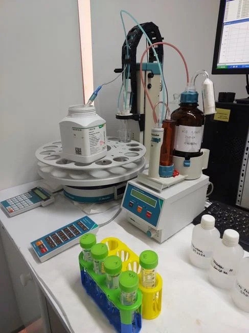
Each treatment stage should have one primary control objective and a defined inlet and outlet condition. Equalization and pH adjustment are prerequisites where blowdown flow or chemistry varies; detention time must be based on measured flow and the operating strategy. Neither equalization nor dosing should be added merely to make a package appear complete.
DAF is appropriate where suspended solids, colloids, oil and grease or related floating material require separation. HydropureWater’s 2026 DAF range covers 4–300 m³/h across 13 standard models, but the selected model must be checked against Katsina flow, water analysis, footprint and controls. A DAF system for cooling blowdown solids removal should be specified by treated-water objective, not catalogue capacity alone.
Multimedia filtration or UF can address residual suspended solids, turbidity and colloids before sensitive reuse or membrane protection. HydropureWater’s 2026 UF catalogue gives a range of 2,000–40,000 L/h, accepts up to 300 ppm turbidity, and includes automatic backwash and air scour. An ultrafiltration system for blowdown pretreatment still requires feed-water compatibility, flux and recovery checks using representative Katsina samples.
Automatic chemical dosing may be required for coagulant, flocculant, pH adjustment and specialty chemicals. Dosages must be established by jar testing and the cooling-water treatment program; coastal or Lagos chemical assumptions are not a substitute for Katsina water and blowdown testing.
RO becomes relevant when blowdown-to-cooling-makeup reuse is technically and commercially justified. HydropureWater’s Lagos reference, 2026 cites 75–85% BWRO recovery and 10–50 mg/L TDS permeate for cooling-tower make-up. These are cited benchmarks, not guaranteed Katsina performance. Final acceptance criteria must reflect measured scaling chemistry, recovery, membrane feed, energy demand and the concentrate route. The lamella clarifier design guide can help assess clarification alternatives, while the odor and corrosion-control guide provides context for chemical storage and worker-safety provisions.
| Treatment stage | Primary objective | Required design input | Residual or destination check |
|---|---|---|---|
| Equalization and pH adjustment | Stabilize flow and chemistry | Measured flow range, pH and operating strategy | Chemical handling and downstream compatibility |
| DAF | Remove suspended and floating material | Solids, colloids and oil-and-grease characterization | DAF sludge collection and disposal |
| Multimedia filtration or UF | Reduce suspended solids and turbidity | Turbidity, solids, flux and recovery tests | Backwash waste and spent media route |
| Automatic dosing | Control coagulation, flocculation and pH | Jar tests and cooling-water chemical program | Residual-chemical control |
| RO | Produce make-up-grade water | Feed chemistry, scaling, recovery and energy demand | Defined RO concentrate route |
| ClO₂ | Disinfect the selected effluent | Disinfection objective, contact conditions and receiving route | Residual disinfectant and dechlorination requirements |
ClO₂ should be used only where on-site disinfection is required for the selected effluent route. Residual disinfectant and dechlorination requirements must be tied to the receiving environment and current permit. RO concentrate, DAF sludge and spent media each need a defined collection, storage and authorized management route; none should be left as an afterthought.
Choose reuse or discharge using a site-specific decision framework
The reuse-or-discharge decision starts with the final destination. Cooling make-up requires the strictest compatibility review because the treated stream enters the cooling loop; another approved process use may tolerate different quality; sewer connection and surface-water discharge require separate receiving-point and permit confirmation. “Reduce water use” is not, by itself, an approval to reuse the stream.
For cooling make-up reuse, verify scaling chemistry, conductivity/TDS, silica, calcium, alkalinity and residual treatment chemistry against the actual cooling system before selecting RO or another polishing process. The result must satisfy both the treatment objective and the cooling-water operating program.
For discharge, identify the authorized receiving point and obtain current FMEnv, NESREA and applicable Katsina state or local permit conditions before setting an effluent target. HydropureWater’s Port Harcourt article, 2026 describes screening, equalization, DAF, multimedia filtration and either side-stream RO or ClO₂ disinfection for that coastal application. It is a process-train example only: Port Harcourt feed chemistry, climate, discharge route and site water balance do not establish Katsina requirements.
The business case should include total cost and environmental consequences rather than equipment price alone. Open Engineering Inc.’s 2026 life-cycle analysis found that the wastewater scenario had approximately twice the global-warming potential of the freshwater case, with treatment energy accounting for roughly 80% of the difference. That finding supports explicit comparison of energy demand, recovery, concentrate management, water value and disposal cost.
| Destination | Go/no-go check | Treatment implication | Procurement decision |
|---|---|---|---|
| Cooling make-up | Does measured chemistry satisfy the actual cooling program? | Polishing and usually RO; concentrate management required | Price against verified recovery and lifecycle energy |
| Approved lower-grade reuse | Is the destination authorized and quality fit for purpose? | Targeted solids, chemistry and disinfection treatment as required | Compare reuse value with treatment and handling cost |
| Sewer connection | Is discharge accepted, and under what conditions? | Meet the sewer authority’s stated acceptance criteria | Obtain written confirmation and connection conditions |
| Surface-water discharge | Is the point authorized, and what are current effluent limits? | Treatment target follows the current permit | Price against the permitted discharge envelope |
| Waste collection | Is the residual classified and collectable? | Containment and pretreatment as required | Price logistics and lawful disposal |
The Pontianak reuse-and-discharge decision review provides a useful comparative structure, but its local water, regulatory and site assumptions require independent verification before use in Katsina.
Build the procurement and approval plan
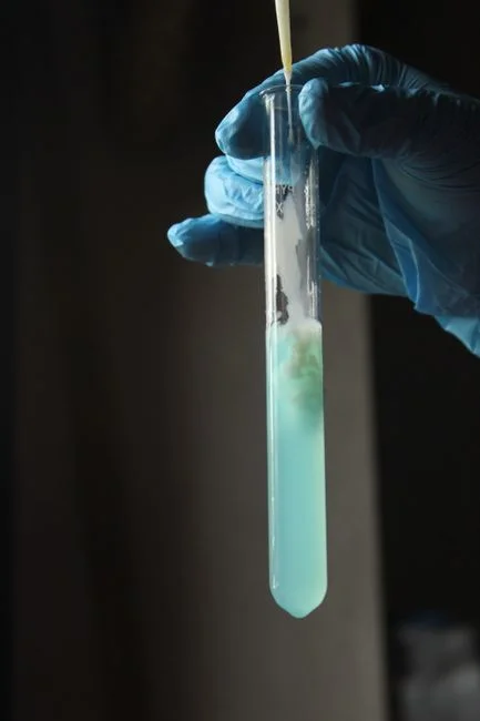
Procurement should begin only after the stream destinations, characterization results and water balance are sufficiently defined to issue separate performance criteria. A combined tender may collect quotations, but sanitary treatment and cooling-blowdown treatment should not share one undifferentiated performance guarantee.
Each equipment package should state its flow range, analyzed inlet-water matrix, required outlet quality, operating availability, controls and acceptance method. The screw-press capacity and sizing guide illustrates the broader procurement principle: capacity claims must be tied to a defined feed and operating condition rather than catalogue throughput.
Ask suppliers to demonstrate performance with representative Katsina source water and blowdown samples, or to define a rigorous site acceptance test. Clean-water capacity claims do not establish performance with the project water matrix. Also check whether quotations include pretreatment, sludge or concentrate handling, residual-chemical management, instrumentation, PLC controls, local spares, operator training and commissioning support.
- Complete site characterization and install representative flow and quality monitoring.
- Confirm the receiving points and obtain current permit conditions.
- Approve the site water balance, operating CoC and destination for each stream.
- Select the treatment concept and residual-waste routes.
- Run pilot or bench testing where the water matrix or recovery remains uncertain.
- Complete detailed design, hydraulic and contaminant mass balances.
- Issue stream-specific procurement packages and acceptance criteria.
- Commission, verify compliance and begin operating monitoring.
Supplier selection should be evidence-led. Request site-representative performance data, pretreatment and sludge or concentrate provisions, control narratives, local support arrangements, operator training and a total-cost comparison. The 2026 cooling-blowdown treatment engineering guide can support the technical questionnaire, but Katsina bids should not be evaluated against Lagos or Port Harcourt performance assumptions.
No final permit limit or equipment capacity should be claimed until the current site-specific approval and sampling exercise is complete. This protects the project from unsuitable coastal assumptions and makes the eventual supplier guarantee traceable to the actual Katsina design basis.
Frequently Asked Questions
Can one combined treatment plant handle both sanitary sewage and cooling blowdown?
Not as the default. Sanitary sewage and cooling blowdown differ in chemistry, temperature, treatment chemicals and likely destinations. Combine them only after separate mass balances establish compatible treatment objectives and a compliant final route.
How should a Katsina blowdown treatment system be sized?
Use the approved heat-rejection load, measured evaporation, operating CoC, cooling configuration, water balance, operating hours and variability. Genesis Water Technologies’ 2026 theoretical blowdown ratio is 1/(CoC − 1); final equipment sizing must then account for the measured operating profile and explicit abnormal-operation strategy.
Can Lagos or Port Harcourt figures be used for Katsina?
They can frame questions and preliminary options, but they cannot establish Katsina water chemistry, discharge limits or capacity. Require current Katsina source-water and blowdown results, confirm the authorized receiving point and obtain current FMEnv, NESREA and applicable state or local permit conditions.
When is reverse osmosis justified for blowdown-to-cooling-makeup reuse?
RO is justified when make-up reuse is an approved destination and measured chemistry, scaling risk, recovery, concentrate handling, energy demand and lifecycle economics support it. A Lagos recovery or permeate benchmark should be treated as a reference case, not a guaranteed Katsina result.
What should a buyer request from a supplier before accepting an offer?
Request site-representative performance data, separate acceptance criteria for each stream, pretreatment and sludge or concentrate provisions, residual-chemical management, PLC controls, local spares, operator training and a total-cost comparison. Also require a clear protocol for proving the promised outlet quality under the characterized Katsina water matrix.