
What Constructed Wetland Capacity Means
Constructed wetland capacity and sizing must be based on treatment duty, hydraulic retention time, storage volume, and site-specific conditions—not area alone. The US EPA identifies hydrology as the most important design factor and links treatment effectiveness to retention time. The wetland configuration must also be selected before calculating volume. For stormwater, Louisville MSD provides explicit equations for required storage, provided storage, porosity, ponding depth, and pretreatment storage. Continuous industrial wastewater requires project-specific flow, pollutant, hydraulic, and soil data before detailed design.
Capacity has three distinct meanings in preliminary engineering. Available storage volume is the physical void space available to hold water. Hydraulic residence or retention time is the time water spends within that space under the design flow condition. Treatment performance is the ability of the complete system to meet the specified contaminant objectives. A basin can provide substantial storage while delivering poor treatment if flow bypasses or short-circuits the active treatment zone.
The EPA’s A Handbook of Constructed Wetlands calls hydrology the most important design factor because it links wetland functions and can determine whether the system succeeds or fails. The handbook also states that treatment effectiveness is related to retention time. It therefore does not support sizing from a single generic loading rule. Its guidance is general, and every site requires individual evaluation.
That distinction matters when comparing industrial process flow with event-based stormwater. A runoff-volume equation estimates storage associated with a specified rainfall event. It does not, by itself, establish the treatment capacity of a wetland receiving continuous wastewater. The broader industrial ETP and DAF selection considerations for factory wastewater should therefore be reviewed alongside the wetland calculation.
| Capacity term | Engineering question | Data required | What it does not prove |
|---|---|---|---|
| Available storage volume | How much water can the proposed geometry hold? | Plan area, media depth, supported porosity, ponding depth, pretreatment-device volume | That water is hydraulically accessible or receives sufficient treatment |
| Hydraulic residence or retention time | How long does design flow remain in the active treatment zone? | Continuous and peak flow, operating schedule, flow distribution, water depth, available effective volume | That discharge quality will meet the objective |
| Treatment performance | Can the system remove the target contaminants to the required level? | Influent characterization, target limits, pollutant-loading basis, media, vegetation, redox conditions, pretreatment | That the nominal footprint alone is sufficient |
Choose the Wetland Configuration Before Sizing
Water’s Constructed Wetlands for Wastewater Treatment classifies systems by vegetation, hydrology, and subsurface-flow direction, so configuration is a design decision rather than a post-calculation detail.
The vegetation categories are emergent, submerged, floating-leaved, and free-floating. Hydrology is classified as free-water-surface or subsurface flow. Subsurface-flow wetlands are further divided by vertical or horizontal flow direction. These characteristics define different flow paths, water-depth conditions, and treatment opportunities.
For preliminary selection, begin with the treatment objective and wastewater character. A free-water-surface system exposes water to the atmosphere and supports visible surface flow, while a subsurface-flow system routes wastewater through a permeable medium. In a vertical flow wetland, flow moves downward through the media; in a horizontal flow wetland, it travels laterally. A horizontal subsurface-flow arrangement should not be assumed interchangeable with a vertical arrangement merely because both are subsurface-flow systems.
Configuration selection must also account for hydraulic variation, footprint, soils, groundwater, and maintenance access. A free-water-surface configuration may offer visible operational conditions but needs its own flow-distribution and short-circuiting review. Subsurface-flow configurations require defensible media, underdrain, ponding, and distribution assumptions.
Contaminant chemistry sets another boundary. The EPA warns that persistent materials such as phosphorus and metals can become wetland sources if the system is not properly constructed and managed. It also identifies toxic pesticides and heavy metals as substances capable of damaging the microbial community; the handbook states that care must be taken to prevent damaging concentrations from entering the wetland. Characterizing these substances before configuration selection prevents a sizing exercise based on an unsuitable contaminant-removal mechanism.
| Design condition | Configuration consideration | Review required |
|---|---|---|
| Visible surface flow is acceptable and objective depends on surface contact, settling, or vegetation uptake | Evaluate a free-water-surface wetland | Depth distribution, short-circuiting, odor, vector control, access |
| Subsurface treatment is appropriate | Evaluate a subsurface-flow wetland | Media specification, porosity, underdrain, distribution, clogging and maintenance |
| Downward media passage is part of the treatment concept | Evaluate a vertical flow wetland | Hydraulic head, media depth, distribution, drainage, maintenance |
| Longitudinal treatment through the bed is part of the concept | Evaluate a horizontal flow wetland | Effective path length, bed depth, underdrain collection, bypass routes |
| Persistent, toxic, or inhibitory contaminants are present | Do not select by configuration alone | Influent characterization, removal mechanism, pretreatment basis, compliance review |
Collect the Inputs Required for an Industrial Wetland Design
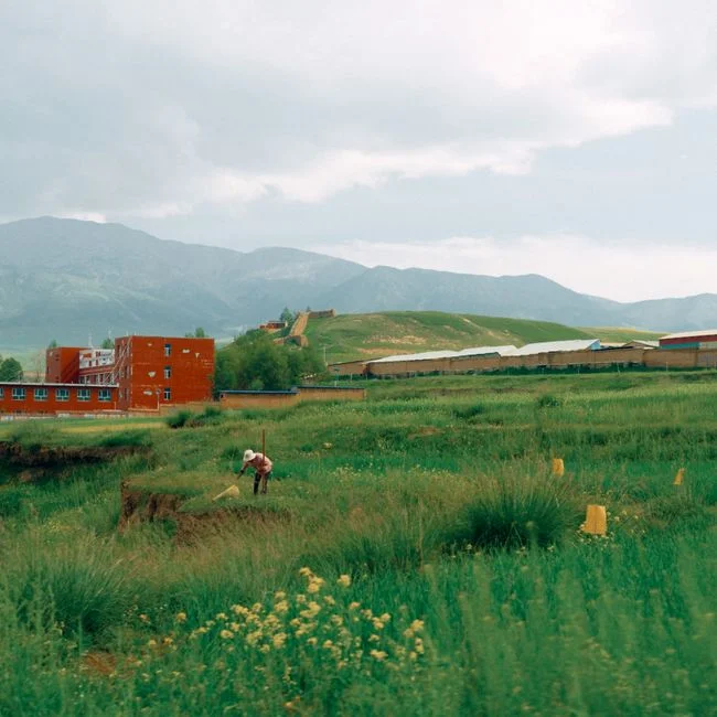
A defensible preliminary size requires a complete design-input sheet covering continuous flow, peak flow, treatment objectives, site constraints, and upstream treatment.
Request the continuous design flow, peak flow, operating schedule, expected wastewater variability, and the source of each stream. State whether the design covers sanitary wastewater, industrial process wastewater, stormwater, or a blend. A daily or annual mass-loading basis is also needed when the objective is contaminant removal rather than flow treatment alone.
For treatment performance, provide current influent concentrations, target pollutants, applicable discharge or reuse criteria, and the proposed treatment objectives. No generic sizing value should be inserted where those project inputs are absent. Flow, concentration, and operating variability together determine the hydraulic and contaminant-loading basis.
The site package should establish the available footprint, topography, gravity-flow opportunities, soil conditions, liner requirements, groundwater constraints, climate, vegetation access, and operations and maintenance needs. The EPA states that a low, gently sloping site near the wastewater source can support gravity flow, while also emphasizing that each site must be evaluated individually.
Groundwater protection requires particular attention. The EPA advises sealing constructed wetlands to avoid contamination of groundwater and to prevent groundwater infiltration into the wetland. Liner and groundwater decisions therefore belong in the preliminary concept, not as later civil-work assumptions.
Include pretreatment in the same data request. Louisville MSD’s calculation adds the pretreatment-device volume, PD, to the storage provided by the wetland. Depending on the wastewater, preliminary screening may require GX rotary mechanical bar screening for gross solids or DAF pretreatment for industrial wetland systems. These are scope options, not automatic wetland-sizing rules.
| Input group | Minimum information to request | Why it affects sizing |
|---|---|---|
| Hydraulic basis | Continuous flow, peak flow, operating schedule, stream type, flow variability | Determines effective volume, retention-time check, peak conveyance, and pretreatment peak demand |
| Treatment basis | Influent concentrations, target pollutants, discharge or reuse criteria, treatment objectives | Establishes the required removal mechanism and contaminant-loading basis |
| Geometry and media | Footprint, proposed configuration, media depth, supported porosity, ponding depth | Converts area into storage and tests whether available volume can meet the retention criterion |
| Site and groundwater | Topography, soils, liner, groundwater, climate, access | Controls gravity flow, containment, construction feasibility, vegetation, and maintenance |
| Operations | Access, monitoring, vegetation establishment, solids removal, instrumentation | Identifies lifecycle constraints that may reduce effective capacity |
| Compliance | Applicable permits and agency requirements | Prevents a preliminary treatment assumption from bypassing regulatory review |
Calculate Storage Capacity with a Transparent Method
Louisville MSD’s Calculation for Constructed Wetland Storage Capacity, published in September 2022, provides a traceable stormwater workflow; it is not a continuous industrial-wastewater sizing method.
- Determine the required water quality volume.
- Calculate the storage provided by the wetland and pretreatment device.
- Apply the applicable green management practice management capacity.
- Compare managed volume with required volume.
- Revise storage parameters or add alternate green infrastructure if the comparison fails.
Step B of the Louisville MSD sheet requires a minimum required water quality volume rain event of 0.6 inches. Its required-volume equation is:
WQVRequired = (A/12)(REWQV)(RV)
Here, A is contributing drainage area in square feet, REWQV is the required water quality volume rain event in inches, and RV is the runoff coefficient calculated as:
RV = 0.05 + 0.009(I)
In that expression, I is impervious cover expressed as a percentage. These variables belong to a contributing-drainage-area calculation. Applying them directly to a continuous process stream would misrepresent the source method.
The Louisville MSD provided-storage equation is:
WQVProvided = A[φ(M) + P] + PD
A is wetland area in square feet; φ is media porosity; M is media depth in feet; P is ponding depth in feet; and PD is pretreatment-device volume in cubic feet. The worksheet identifies 40% media porosity in its worked basis. The engineer should replace that value only with a porosity supported for the selected media and construction condition.
The next source step calculates managed water quality volume as:
MWQV = (1/100)(GMP Management Capacity)(WQVProvided)
The management-capacity percentage is obtained from the applicable referenced table, with supporting model printouts or other documentation requested to verify retention times. If MWQV is less than WQVRequired, the Louisville MSD workflow directs the designer to adjust the provided-storage parameters or proceed to alternate green management practices. If the comparison passes, the sheet proceeds to O&M documentation.
| Louisville MSD variable | Definition in the source equation | Application boundary |
|---|---|---|
| WQVRequired | Water quality volume required for the specified drainage event | Stormwater calculation |
| A | Contributing drainage area in Step C; constructed-wetland area in Step D | Use the area associated with each equation |
| REWQV | Required water quality volume rain event, with a minimum of 0.6 inches | Stormwater calculation |
| I and RV | Impervious cover and calculated runoff coefficient | Contributing-drainage-area calculation |
| φ and M | Media porosity and media depth | Provided storage; porosity requires project support |
| P | Ponding depth | Provided storage |
| PD | Volume of the pretreatment device | Included in provided storage |
| MWQV | Managed volume after applying the applicable GMP management capacity | Compared with required stormwater volume |
For continuous industrial wastewater, make a separate preliminary check. Multiply the project design flow by the required wetland hydraulic retention time to establish the required effective water volume, then compare that volume with the hydraulically available wetland volume. Use the project retention criterion rather than a generic value not established by the supplied research. Label the result preliminary until detailed hydraulic calculations establish effective volume, flow paths, and distribution.
Verify Hydraulic Performance Before Accepting the Size
Nominal volume does not establish effective treatment because the EPA identifies hydrology—the distribution and residence of water—as the central design factor.
First check how flow enters, traverses, and leaves each cell. Identify dead zones, preferential paths, and short-circuiting routes. Confirm that the selected free-water-surface or subsurface-flow arrangement can receive the continuous and peak design flows under the proposed head conditions. A gravity-flow concept must account for available elevation; a nominal plan area cannot compensate for insufficient hydraulic grade.
Next, reconcile retention time with the actual treatment volume. The EPA states that treatment effectiveness is related to the time water remains in the wetland. Record which volume is effective: ponding storage may not behave like media pore volume, and underdrain or distribution structures may occupy part of the geometric volume. The retention-time calculation should identify both its flow basis and its available-volume basis.
Verify that ponding depth, media depth, vegetation, and underdrain arrangement match the design basis. Horizontal and vertical subsurface-flow systems require different distribution and collection checks. Also review seasonal effects, vegetation establishment, clogging risk, solids accumulation, and maintenance access. The EPA states that wetland performance can change over time as the substrate and accumulated pollutants alter the system.
Performance remains site-specific. The EPA states that no two sites are identical and that a local natural wetland can serve as a design model only after modification for the project site and its specific conditions. The final review should therefore include a calculation and assumption register.
| Register item | Minimum record | Acceptance question |
|---|---|---|
| Geometry | Plan area, media depth, ponding depth, cell arrangement | Do the dimensions match the approved calculation basis? |
| Porcelain | Media identity, void ratio or porosity, construction method | Is the storage value supported by the selected material and condition? |
| Hydraulics | Design flow, peak flow, retention criterion, effective volume, flow paths | Has short-circuiting and distribution been checked? |
| Treatment objectives | Contaminants, influent concentrations, discharge or reuse criteria | Does the proposed treatment mechanism address each objective? |
| Pretreatment | Device, duty, stored volume PD, residual load | Is the downstream wetland loading basis reduced and documented? |
| Performance risk | Clogging, vegetation, solids, seasonal and maintenance assumptions | Can effective capacity be sustained and inspected? |
Use a Wetland-plus-Treatment Decision Framework
Treatment objectives determine whether a constructed wetland should stand alone or function as one stage in a treatment train.
The first decision gate is the required contaminant removal. If the objective depends on removing suspended solids, oil and grease, or colloidal material, upstream separation may be needed to control solids accumulation and protect wetland hydraulics. The second gate is toxicity: pesticides, heavy metals, and other inhibitory substances require careful characterization and design review. The remaining gates are flow variability, footprint, soils, groundwater, discharge constraints, and operability.
DAF is a candidate where suspended solids, oil and grease, or colloidal material must be removed before wetland treatment. HydropureWater’s DAF systems cover 4–300 m³/h across 13 standard models. This equipment range may inform pretreatment-duty screening, but it does not establish wetland area or hydraulic retention time.
A GX rotary mechanical bar screen is relevant where rags, plastics, fibers, and other gross solids could obstruct wetland distribution or overload downstream treatment. It is designed for continuous-duty industrial and municipal screening. Its selection still depends on the actual wastewater solids character and required peak duty.
When the project requires membrane-grade solids separation or reverse-osmosis pretreatment, review ultrafiltration systems for RO pretreatment. The stated UF systems operate from 2,000 to 40,000 L/h, use 0.03 micron PVDF membranes, and accept up to 300 ppm turbidity. These are treatment-equipment specifications, not wetland sizing criteria.
Before procurement, require site-specific design, regulatory review, liner and groundwater assessment, and an operations plan. The industrial ETP and DAF selection guidance for factory wastewater can help structure that equipment discussion, but the wetland calculation remains a separate civil and process-engineering work product.
| Decision condition | Go/no-go implication | Next engineering action |
|---|---|---|
| Target contaminants and flow characteristics are compatible with the selected wetland mechanism | Proceed to preliminary wetland sizing | Calculate effective volume and retention time; verify hydraulics |
| High suspended solids, oil and grease, or colloidal load could impair the wetland | Add upstream separation | Define pretreatment duty and recalculate downstream loading and storage |
| Rags, plastics, fibers, or other gross solids are present | Add screening | Select screening duty and confirm downstream flow distribution |
| Fine solids removal is required before RO or another high-separation process | Consider UF or a comparable solids-separation stage | Confirm feed quality, hydraulic compatibility, and pretreatment responsibility |
| Footprint, groundwater, soils, or regulation prevents a defensible wetland concept | Do not force the wetland solution | Evaluate compact treatment alternatives or revise the project basis |
Build a Bid-Ready Design and Procurement Package

Comparable proposals require one calculation and scope basis covering civil works, pretreatment, monitoring, and long-term operations.
Issue the design flow, peak flow, operating schedule, influent characterization, treatment objectives, applicable criteria, site constraints, selected wetland configuration, calculated storage, and retention-time basis. Attach the calculation register so bidders price the same design rather than substitute their own hidden assumptions.
State the basis for every major input, including media depth, porosity, ponding depth, pretreatment storage, and the applicable GMP management-capacity percentage where the Louisville MSD method is used. Require proposed media, underdrains, liner, distribution, planting, pretreatment, instrumentation, access, and commissioning to be clearly separated in the scope.
Operations documentation is an explicit requirement in the Louisville MSD workflow: after the volume comparison passes, Step H calls for completion of O&M documentation. The bid package should also define monitoring, performance testing, vegetation establishment, solids removal, media inspection, liner and underdrain maintenance, and responsibility for resolving deviations from the approved calculation basis.
Supplier statements about wetland area, hydraulic residence, or treatment capacity should remain preliminary until supported by the complete project inputs and engineering calculations. The wider 2026 effluent treatment plant engineering guide provides adjacent context, but it does not replace a project-specific wetland calculation.
| Bid package component | Required content | Buyer check |
|---|---|---|
| Design basis | Flow, pollutants, objectives, criteria, site constraints | Can every proposed capacity statement be traced to this basis? |
| Calculation package | Storage equations, continuity, effective volume, retention time, assumptions | Are units, data sources, and deviations identified? |
| Civil and hydraulic scope | Basin, media, liner, distribution, underdrain, planting, access | Are interfaces and performance responsibilities explicit? |
| Equipment scope | Pretreatment, pumping, instrumentation, controls, power | Are duties matched to continuous and peak project flows? |
| Commissioning and O&M | Testing, startup, monitoring, maintenance, documentation | Are acceptance tests and recordkeeping deliverables defined? |
| Deviation process | Authority to change assumptions and required approval | Is there a controlled process for design deviations? |
Frequently Asked Questions
How much constructed wetland area is required for industrial wastewater?
No universal area can be stated from the supplied sources because continuous industrial sizing is site-specific. The preliminary calculation must connect design flow, the project retention-time criterion, effective storage volume, treatment objectives, media and ponding geometry, hydraulic distribution, and site constraints.
What information should a supplier request before quoting a constructed wetland?
Request continuous and peak flows, operating schedule, wastewater variability, influent concentrations, target pollutants, applicable criteria, proposed configuration, available footprint, topography, soils, groundwater conditions, liner requirements, access, pretreatment needs, and the proposed monitoring and maintenance scope. Do not accept an area-only quote.
How do stormwater storage equations differ from continuous industrial wastewater sizing?
The Louisville MSD equations use contributing drainage area, a required rainfall event, impervious cover, wetland geometry, and GMP management capacity to compare required and managed stormwater volume. Continuous industrial wastewater instead begins with continuous process flow and a project-specific retention criterion. The stormwater result cannot be transferred to continuous treatment without an independent hydraulic and treatment basis.
When is pretreatment likely to be necessary for a constructed wetland?
Pretreatment is likely when the wastewater contains suspended solids, oil and grease, colloids, or gross solids that could clog media, impair distribution, or change the treatment loading basis. Toxic pesticides, heavy metals, and other inhibitory contaminants also require careful characterization. Check the actual objectives and influent data before choosing screening, flotation, membrane separation, or another process.
What should be resolved before selecting a wetland supplier?
Confirm site-specific design, liner and groundwater protection, regulatory requirements, flow and pollutant design basis, pretreatment interfaces, commissioning tests, monitoring, and O&M responsibility. Ask each bidder to show how its stated area, hydraulic residence, and treatment capacity follow from the same approved inputs and calculation methodology.