What a Semiconductor UPW Tool Connection Actually Is
A semiconductor ultrapure water (UPW) tool connection is the engineered interface where the fab's UPW distribution loop ends and the manufacturing tool's internal piping begins. The standardized definition comes from SEMI Draft Document 6129 (the F61 revision), §5.1.3, which states: "UPW system equipment boundaries start at the feed to the raw water tank (if exists) or otherwise at the feed to the raw water pump. The system boundaries end at the point of connection valves supplying UPW to the manufacturing tool or any other fab or facility user utilizing UPW to support production." (SEMI 6129, 2017-02). A tool connection is the handoff at those point-of-connection (POC) valves, where the fab's UPW system is contractually responsible for water quality and the tool original equipment manufacturer (OEM) takes ownership of internal tool conditions.
SEMI 6129 §5.1.2 defines UPW as "purified water meeting microelectronic industry requirements documented in SEMI F63 and ASTM D5127 for the line width of one micrometer and smaller" (SEMI 6129, 2017-02). The same F63/ASTM D5127 quality set governs the tool-side water the connection must preserve, so the hook-up spec is a quality-preservation contract across one mechanical seam. SEMI 6129 §5.1.4 defines deionized (DI) water as "any purified water that has level of ions reduced down to the resistivity of minimum 1 MΩ·cm" and specifies "this quality of water is not applicable for advanced semiconductor manufacturing" (SEMI 6129, 2017-02). Citing DI in a 2026 tool-connection spec is a red flag that the spec writer has confused the two tiers.
The three broad process stages that produce the water being handed off are pretreatment, primary treatment, and polishing/transport, per the Wikipedia UPW overview (en.wikipedia.org, Ultrapure water). Each stage contributes specific removal functions, and the tool connection sits at the end of the polishing/transport chain, immediately downstream of the final filter.
The Five Standard Measurement Points Around a Tool Connection
SEMI 6129 §5.1.12.2 defines five points of measurement in the polish loop in flow order: POD, POC, POE, POU, and POP. These are the only standardized sample-port identifiers used in a tool-connection spec, and confusing them is a common error in hook-up documents. Proper identification of these points ensures technical alignment between the fab's infrastructure and the OEM's requirements.
| Point | SEMI 6129 §5.1.12.2 definition (2017-02) | Physical location | Ownership / F61 scope |
|---|---|---|---|
| POD — point of distribution | "sample port near the outlet of the final filter" | Distribution loop header, just downstream of the polish-loop final filter | Fab UPW system (in F61 scope) |
| POC — point of connection | "sample port near a take-off valve on the lateral used to connect to the manufacturing tool" | Lateral branch to each tool, at the take-off valve | Fab UPW system (in F61 scope; marks the contractual handover) |
| POE — point of entry | "sample port near the feed connection to the manufacturing tool" | Tool feed flange/fitting, just before the tool's internal piping | Transition zone; often defined as the last point on the fab side |
| POU — point of use | "sample port within the tool near the entry to the process chamber" | Inside the tool, on the wetted polymer/stainless transition before the chamber | Tool OEM (outside F61 scope per §3.4) |
| POP — point of process | "water in production chamber" | Process chamber itself | Tool OEM; not directly sampled, inferred from POU and process control |
The ownership boundary implied by these definitions matters when faults are assigned. POD and POC are unambiguously on the fab's UPW system side and inside F61 scope; POU and POP sit inside the tool and are outside F61 scope per §3.4 (SEMI 6129, 2017-02). POU sample ports are described as "within the tool near the entry to the process chamber" (SEMI 6129 §5.1.12.2.4, 2017-02), so they sit exactly on the wetted polymer/stainless transition where the dominant contamination source shifts from distribution-loop materials to tool-internal materials. UPW is circulated continuously through the polish loop to prevent stagnation and bacterial growth, per the Wikipedia UPW article, so POD, POC, and POE measurements reflect the same recirculating bulk quality unless a tool is actively drawing. POP is rarely sampled directly; it is inferred from POU trends and tool-level process control data, which is why F61 stops at POU and defines POP only for context.
What F61 Covers — and What It Explicitly Leaves Out at the Tool Connection
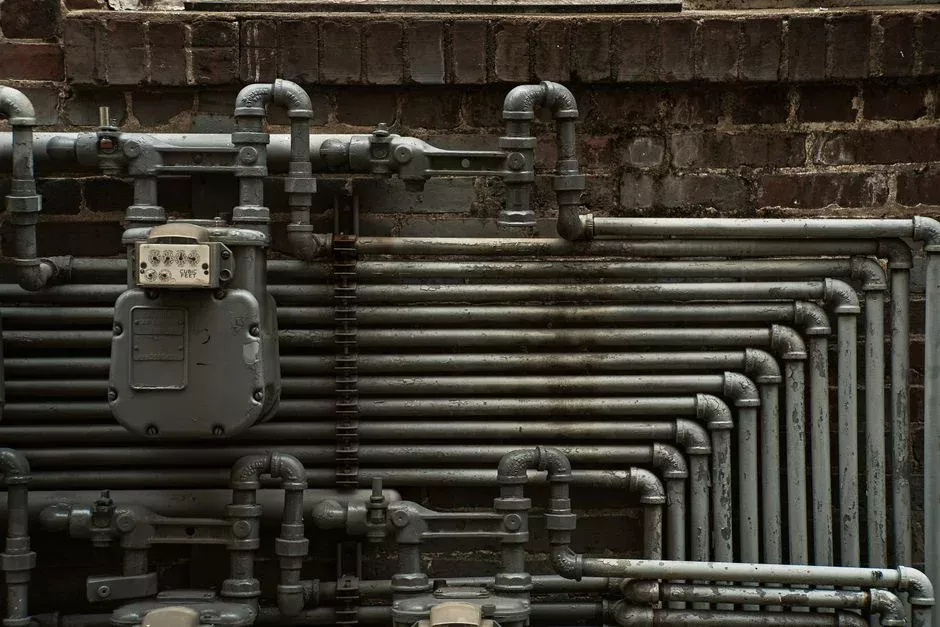
SEMI 6129 §3.4 states: "This Guide is limited to the scope of UPW treatment and distribution system; it does not address the considerations of the UPW materials and components within manufacturing tools" (SEMI 6129, 2017-02). In practice, this means the F61 hook-up ends at the POC valves, not at the tool's wetted internals; any spec clause that reaches inside the tool to prescribe piping, fittings, or elastomers exceeds the standard. Understanding these boundaries prevents contractual friction during tool installation.
The second carve-out is §3.7: "This Guide does not provide recommendations for the design or operation of POU specialty systems, such as Carbonated UPW water, Ozonated UPW water, low TOC UPW water, and low particle UPW Water" (SEMI 6129, 2017-02). Each of these four POU specialty waters has its own material and operating considerations; a tool that consumes, for example, ozonated UPW for a specific cleaning step needs the tool OEM's spec referenced alongside, not in place of, F61. The broader standards tree cited in §4.1 includes SEMI F19 (stainless wetted surface finish), SEMI F57 (polymer materials and components in UPW and liquid chemical distribution), SEMI F63 (UPW quality), and SEMI F75 (UPW quality monitoring), so the tool connection sits at the seam between F57/F63 and the tool OEM's internal material spec (SEMI 6129, 2017-02). For wetted-material selection on the fab side of that seam, the UPW piping material comparison guide covers the F19/F57 trade-offs in detail. SEMI 6129 §3.6 also notes that F61, F63, and F75 "will be updated at the same time to ensure continuity for the users of all three Documents" on a 2-year review cycle, so any 2026 spec should be re-validated against the current IRDS-aligned revision rather than the 2017 ballot text.
F63 / ASTM D5127 Quality Attributes the Tool Connection Must Preserve
The tool connection serves as a quality-preservation boundary: the fab's UPW arrives at POD at specification, and the hook-up must hand it to the tool at POE with no measurable degradation. The canonical F63 targets, as cited by AXEON's UPW guide, are resistivity >18.2 MΩ·cm at 25 °C, total organic carbon (TOC) <1 ppb, dissolved silica 0.2–1.0 ppb, colloidal silica 0.3–2.0 ppb, and particle counts <1 particle/mL for particles >0.05 µm, with bacterial counts <1 CFU/100 mL (AXEON, Ultrapure Water Systems in Semiconductor Manufacturing Explained). These values represent the contractual handover set the POC sample port confirms.
| Parameter | F63 / AXEON-cited target | Why the tool connection must preserve it |
|---|---|---|
| Resistivity | >18.2 MΩ·cm at 25 °C | 0.1 ppb NaCl drops resistivity from 18.18 to 18.11 MΩ·cm (Wikipedia UPW); any leachables across the POC–POE seam show up immediately in POE trends. |
| TOC | <1 ppb (UV-persulfate on-line) | Organics leach from polymer tubing and from installation contamination; pre-commissioning flush and material choice at the hook-up dominate this value. |
| Dissolved silica | 0.2–1.0 ppb (ICP-MS) | Silica leaches from glass and certain elastomers; tool-side fittings must be selected against this limit. |
| Colloidal silica | 0.3–2.0 ppb (ICP-MS) | Sub-ppb colloidal silica is hard to measure but easy to add through mechanical disturbance of the lateral; POE trends are the early warning. |
| Particles >0.05 µm | <0.3 particles/mL (laser counter) | Per Wikipedia UPW, the critical particle size is one-half the smallest feature (e.g., 40 nm feature → all particles >20 nm removed); the hook-up cannot be a particle source. |
| Bacteria | <1 CFU/100 mL (membrane filtration) | Stagnation in a dead-legged lateral defeats the polish loop; the connection geometry must maintain circulation. |
The infrastructure that delivers those values to the connection is described in AXEON's treatment-train table: reverse osmosis at 95–99% dissolved-solids rejection, electrodeionization (EDI) to >2 MΩ·cm without chemical regeneration, ultraviolet (UV) oxidation at 185 nm to push TOC below 1 ppb, ultrafiltration at <0.01 µm to remove colloidal silica, and 0.2 µm final filters before distribution (AXEON, Ultrapure Water Systems in Semiconductor Manufacturing Explained). The matching fab-side equipment for a new hook-up is an industrial RO system feeding an EDI polishing stack, with UPW final filter cartridges and UF elements sized to the lateral flow. For surface-finish limits on the wetted stainless side of the hook-up, the UPW piping surface roughness spec is the cross-reference, and the RO vs EDI sizing guide covers the polishing-loop capacity sizing behind POC.
2026 Spec-Writing Checklist for a Semiconductor UPW Tool Connection
On the fab side (F61 scope), the spec should name the POC valve type and lateral material, require a sample port at POC, and state the F63 / ASTM D5127 quality targets the fab commits to at POC as a contractual handover value. The same clause should require that the F63 numbers be met continuously under the design draw profile, not just at commissioning. On the boundary itself, the spec should define the POE flange or fitting, the leak-test protocol, and the pre-commissioning flush requirements (flow, duration, resistivity and TOC end-point) so that the tool does not see installation-related excursions during ramp-up.
On the tool side (F61 out of scope), the spec should reference the tool OEM's internal POU and POP requirements and confirm they are consistent with the F63 targets committed at POC; any POU specialty water (carbonated, ozonated, low-TOC, or low-particle UPW) must be a separate line item per SEMI 6129 §3.7 (2017-02), not folded into the base F63 handover. On documentation, cite the SEMI 6129, F63, and F75 revision dates the spec was written against, and add a "re-validate against current SEMI edition" instruction so the document ages predictably through the 2-year review cycle noted in §3.6.
Frequently Asked Questions
Frequently Asked Questions
What is the difference between POE and POU in a semiconductor UPW tool connection?
POE (Point of Entry) refers to the main utility distribution point where UPW enters the sub-fab or tool bay area from the central facility loop, typically handling high-flow, steady-state supply. POU (Point of Use) refers to the final connection interface at the specific manufacturing tool, where the water is conditioned or monitored to meet the stringent requirements of the process chamber.
While POE systems focus on maintaining bulk chemical and physical parameters, POU connections are designed to minimize localized contamination (such as particles or bacteria) that could be introduced by the final segments of piping or tool-internal components.
Does SEMI F61 cover the water tubing inside the manufacturing tool?
No, SEMI F61 specifically covers the piping and components up to the tool interface connection. The internal plumbing of the manufacturing tool itself is generally governed by the tool manufacturer’s internal specifications and the general safety standards for semiconductor manufacturing equipment, such as SEMI S2.
The standard defines the "Tool Interface" as the physical connection point where the facility supply line meets the tool’s inlet manifold. Any piping downstream of this interface is considered part of the tool’s internal design rather than the facility-to-tool distribution infrastructure.
Which SEMI standard defines semiconductor UPW quality at the tool connection — F61, F63, or F75?
SEMI F63 is the primary standard that defines the recommended physical and chemical specifications for ultrapure water at the point of use. While SEMI F61 governs the design and installation practices for the high-purity piping systems, F63 establishes the analytical targets for contaminants like TOC, dissolved oxygen, and resistivity.
SEMI F75 is not a primary standard for UPW quality; rather, it relates to the guide for measuring and reporting the performance of UPW systems. For compliance at the tool connection, fab engineers should reference the F63 table for specific concentration limits.
How should a fab-side spec writer define a semiconductor UPW tool connection in an RFQ?
A spec writer should define the connection by citing the required SEMI F61 installation practices for piping materials, such as high-purity PFA or electropolished 316L stainless steel, and referencing the specific F63 water quality parameters required for the tool’s process nodes. The RFQ must specify the interface point location, the required flow rate (L/min), and the maximum allowable pressure drop across the connection.
Additionally, the spec should mandate documentation of weld inspection reports, particle count testing post-installation, and a requirement for a certified "clean-build" installation process to ensure the connection meets the integrity levels specified in SEMI F61.
What POU specialty UPW variants (carbonated, ozonated, low-TOC, low-particle) are excluded from SEMI F61, and which standard covers them instead?
SEMI F61 focuses on the distribution of standard, non-modified UPW. Specialty variants such as carbonated or ozonated water, which involve the injection of gases, are excluded because they introduce chemical equilibrium complexities and corrosivity profiles not addressed by general UPW piping standards.
These specialty chemical delivery systems are typically governed by SEMI F98 (for gas-liquid mixing systems) and specific process-tool safety guidelines. There is no single "UPW-only" standard for these variants, so they are generally managed under the process-specific chemical delivery specifications provided by the equipment manufacturer.