Why Surface Particle Roughness Defines Semiconductor UPW Quality
A 30 cm wafer requires roughly 2,200 gallons (8,328 L) of total fabrication water, of which approximately 1,500 gallons (5,678 L) is ultrapure water (UPW) used for rinsing, chemical dilution and chemical mechanical planarization (Processing Magazine). That water is the dominant process chemical in any fab, and it is the most sensitive to contamination because particles act as circuit killers at the nanometer scale: any particle larger than about one-half the smallest chip feature can bridge or block a circuit, so a 40 nm feature requires removal of all particles greater than 20 nm (Wikipedia UPW, citing SEMI-aligned industry rules).
The final UPW loop is the last surface the water touches before point-of-use, and that surface is where corrosion products, gasket debris, lubricant residue and biofilm fragments shed back into the stream (Desalination, January 2025; Processing Magazine). Surface roughness is the variable that ties mechanical finish to both particle generation and bacterial colonisation, which is why the spec belongs in the piping isometrics rather than only in the polishing skid documentation.
When a process engineer writes a wetted-surface spec for the final UPW distribution loop, three numbers are non-negotiable: average surface roughness Ra, particle count at point-of-use, and a microbial envelope. None of them is independent. Tighten the Ra and you pull down the particle baseline; pull down the particle baseline and you reduce the nutrient scaffolding that biofilm needs to anchor. The rest of this blueprint ties those three numbers into a single spec workflow a fab engineer can defend in a design review.
Ra, Particle Limits and the SEMI F63 Envelope
Surface roughness Ra is the arithmetic average of the deviation of surface height from a mean line, normally expressed in microinches or micrometres; it is the headline figure on a wetted-surface drawing because it is simple to measure, repeatable across instruments, and correlates with both cleanability and bacterial attachment (Processing Magazine). The industry rule of thumb for wetted metallic UPW components is Ra ≤ 35 microinches (~0.89 µm), achieved by electropolishing to a chromium-oxide finish that is reported to be roughly 30× more resistant to chemical attack than unpolished 316L stainless steel (Processing Magazine). The Ra number is paired with the SEMI F63 / F63-0213-aligned particle envelope of total particles ≤ 200 particles/L at point-of-use, supported by final-loop filters of ≤200 nm pore size placed just before distribution (Wikipedia UPW; Desalination, January 2025). The same UPW system is held to a culture-based microbial limit of <1 CFU/100 mL, but culture captures only about 1% of cells in oligotrophic UPW, so flow cytometry (FCM) is increasingly specified alongside heterotrophic plate count (HPC) to catch viable-but-non-culturable (VBNC) organisms (Desalination, January 2025). Total organic carbon (TOC) sits below 5 µg/L at point-of-use, with sub-7 nm device fabs pushing TOC even lower and adding UV-AOP or sulfate-radical AOPs to the polishing train to address small-molecule organics such as urea that pass through ion exchange and RO (Wikipedia UPW).
| Parameter | Limit at point-of-use | Source |
|---|---|---|
| Wetted-metallic Ra | ≤ 35 microinches (~0.89 µm), electropolished | Processing Magazine |
| Final-loop filter pore size | ≤ 200 nm | Wikipedia UPW |
| Total particles | ≤ 200 particles/L | Desalination (Jan 2025); SEMI F63 envelope |
| Microbial (culture) | < 1 CFU/100 mL | Desalination (Jan 2025) |
| TOC | < 5 µg/L (sub-7 nm: lower; AOP polishing considered) | Wikipedia UPW |
| Resistivity | Approaching 18.18 MΩ·cm at 25 °C | Wikipedia UPW |
| Dissolved oxygen | < 10 µg/L for advanced microelectronics rinse | Wikipedia UPW |
Putting these numbers on a P&ID as a single envelope is what turns a finishing detail into a yield control. Resistivity and DO round out the envelope; aggressive UPW actively draws ions from metal surfaces, so a resistivity drop at point-of-use is often the first signal that the wetted surface is shedding rather than staying passive (Wikipedia UPW; Processing Magazine).
How Surface Roughness Drives Particle and Biofilm Behaviour
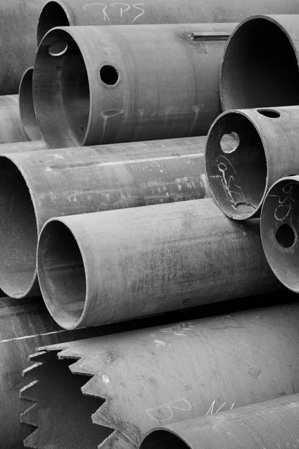
A smoother surface is easier to clean, leaves less area for residual TOC, polishing slurry carryover and bacterial cells to anchor on, and recovers faster after sanitisation (Processing Magazine). The relationship is not subtle: in a 2025 Desalination study of 32 mm CPVC, stainless steel (SUS) and PVDF pipe segments, biofilm on pipe walls — not free-floating cells — was identified as the dominant source of bacteria in the loop, and the material that supported the lowest biomass also leached the least organic carbon (Desalination, January 2025). The same study identified Herbaspirillum, a nitrogen-fixing oligotroph, as 66.15% of the bacterial community in the operating UPW, with Ralstonia forming significant biofilm on SUS and CPVC surfaces (Desalination, January 2025). Roughness scales with corrosion-driven particle release as well: aggressive UPW at resistivity approaching 18.18 MΩ·cm at 25 °C actively draws ions from metal surfaces, and an unpolished or un-passivated surface sheds metallic particles that show up as particle excursions (Wikipedia UPW; Processing Magazine).
Roughness is necessary but not sufficient. Material compatibility, gasket and elastomer selection, and lubricant-free cleanroom assembly have to be controlled in the same workflow or the Ra target alone will not hold the loop in spec. A documented deviation in the Desalination study is illustrative: under identical test conditions, SUS and CPVC supported significantly more biofilm than PVDF, even though all three pipe segments were pre-cleaned and filled with the same UPW, which is direct evidence that the wetted material — not the polishing skid — set the biofilm floor of the loop (Desalination, January 2025).
Material and Finish Selection for the Final UPW Loop
For structural, high-temperature or high-pressure segments of the final loop, the default metallic option is 316L stainless steel, electropolished and passivated, with Ra ≤ 35 microinches; assembly and packaging must take place in a cleanroom to keep lubricant residue and particulates off the wetted surface (Processing Magazine). Polymer options dominate the high-purity contact path: PVDF, PFA, PTFE and high-purity PP are chosen because extractables, metal-ion release and particulate generation are lower than unpolished metal, with PVDF the most documented in controlled tests (Processing Magazine; Desalination, January 2025). The 2025 Desalination study quantified the trade-off directly: PVDF leached approximately 0.08 mg/L TOC and supported a biofilm-formation potential (BFP) near 5×10⁵ cells/cm², while CPVC and stainless steel carried a higher biofilm burden under the same conditions, with significant Ralstonia biofilm on SUS and CPVC surfaces (Desalination, January 2025). A cross-reference for III-V and compound-semiconductor wet benches is in the III-V semiconductor wet processing equipment spec guide.
| Material / finish | TOC leaching (controlled test) | Biofilm-formation potential | Notes for final UPW loop |
|---|---|---|---|
| 316L SS, electropolished, Ra ≤ 35 µin, passivated ASTM A380/A967 | Higher than PVDF in side-by-side test | Higher than PVDF; significant Ralstonia biofilm reported (Desalination, Jan 2025) | Use for structural/temperature/pressure sections; cleanroom assembly mandatory |
| PVDF | ~0.08 mg/L TOC (Desalination, Jan 2025) | ~5×10⁵ cells/cm² BFP — lowest of materials tested | Default for highest-purity final-loop sections |
| PFA / PTFE / high-purity PP | Low; documented as low-extractable | Low; less controlled-test data than PVDF | Use where temperature or chemical compatibility requires fluoropolymer |
| CPVC | Higher TOC migration than PVDF | Higher BFP than PVDF; Ralstonia biofilm observed (Desalination, Jan 2025) | Avoid for the final UPW contact path where biofilm is critical |
| PVC (any grade) | Not a UPW-grade material | Not characterised as UPW-grade | Do not use for any UPW contact |
Avoid graphite-containing components anywhere in the wetted path; they shed particles. Avoid any lubricant-exposed assembly outside a cleanroom. Where pretreatment water is being conditioned for the UPW train, industrial RO systems sized for UPW pretreatment set the bulk water quality, and continuous electrodeionization polishing for the UPW loop drives resistivity to the 18.18 MΩ·cm target. Final-loop material selection is what protects that work from being undone at the last ten metres.
Passivation, Cleaning and Validation of Wetted Surfaces
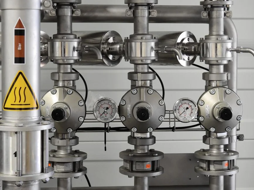
Passivation of finished stainless-steel components follows ASTM A380 or ASTM A967 with a mild oxidant such as nitric acid; the treatment removes embedded iron, iron-oxide scale and other iron-based compounds and restores the chromium-oxide layer that resists further attack (Processing Magazine). After passivation, assemblies are cleaned with a special agent using a process similar to that used when preparing valves for oxygen service, in a dedicated cleanroom where exposure to external dust, particles and lubricant is controlled (Processing Magazine). Assemblies are then specially packaged to preserve cleanliness through shipping and storage.
Field validation of the as-installed loop is a separate document from the factory passivation record. The minimum as-installed checks are: surface Ra measurement on witness coupons or sample fittings from the same production lot; on-line particle counting at point-of-use against the ≤ 200 particles/L envelope; TOC and resistivity trending over the first 30 days of operation; and a periodic biofilm / flow-cytometry check rather than culture-only HPC (Desalination, January 2025). The justification for not relying on culture alone is quantitative: only about 1% of bacteria in oligotrophic UPW are culturable, so a clean HPC plate can mask a developing biofilm that will eventually shed (Desalination, January 2025). Periodic sanitisation with ozone or hydrogen peroxide, paired with the UV sterilisation step in the polishing train, holds the loop between biofilm checks.
Specification Checklist for a 2026 UPW Piping Surface
The following fragment is written so it can be lifted directly onto a piping isometric, a P&ID note or a procurement data sheet. Every line ties back to a specific source so the spec is defensible in a design review.
| Spec line | Requirement | Source |
|---|---|---|
| Wetted metallic surface | Ra ≤ 35 microinches (~0.89 µm); 316L stainless steel; electropolished; passivated to ASTM A380 or ASTM A967; cleanroom assembly and packaging | Processing Magazine |
| Wetted polymer surface | PVDF default; PFA / PTFE / high-purity PP where temperature or chemistry require; documented TOC and BFP data required; CPVC and PVC excluded from final UPW contact | Desalination (Jan 2025); Processing Magazine |
| Particle envelope | ≤ 200 particles/L at point-of-use; ≤ 200 nm final-loop filtration; on-line particle counters at POU | Wikipedia UPW; SEMI F63 envelope |
| Microbial envelope | < 1 CFU/100 mL by culture, cross-checked by flow cytometry total cell counts to catch VBNC organisms | Desalination (Jan 2025) |
| TOC / resistivity / DO | TOC < 5 µg/L at POU; resistivity approaching 18.18 MΩ·cm at 25 °C; DO < 10 µg/L for advanced microelectronics rinse | Wikipedia UPW |
| Documentation pack | SEMI F63 / F63-0213 conformance, ASTM A380 / A967 passivation records, Ra measurement certificates, cleanroom-assembly records, sanitisation plan with periodic FCM checks | Processing Magazine; Desalination (Jan 2025) |
Buying decisions on capacity, lead time and compliance sit alongside the technical lines. A spec sheet that lists Ra, particle count and microbial envelope with the documentation pack named gives a vendor a defensible scope to quote against, and gives the buyer's quality team the records it needs at FAT and SAT.
Frequently Asked Questions
What Ra number should we put on a 2026 final-loop piping drawing?
Specify Ra ≤ 35 microinches (~0.89 µm) on wetted metallic components, achieved by electropolishing to a chromium-oxide finish on 316L stainless steel and passivated to ASTM A380 or ASTM A967; this is the figure Processing Magazine attributes to UPW control-valve service and it is the de facto industry rule of thumb for wetted metallic UPW components. Pair the Ra line with the SEMI F63-aligned particle envelope of ≤ 200 particles/L at point-of-use, supported by ≤ 200 nm final-loop filtration (Wikipedia UPW; Desalination, January 2025).
Which wetted material gives the lowest biofilm risk in the final UPW loop?
In a 2025 controlled test of 32 mm pipe segments, PVDF supported a biofilm-formation potential of approximately 5×10⁵ cells/cm² and leached approximately 0.08 mg/L TOC, while CPVC and stainless steel carried a higher biofilm burden under the same conditions, with significant Ralstonia biofilm on SUS and CPVC surfaces (Desalination, January 2025). For highest-purity final-loop sections, default to PVDF; for structural/temperature/pressure sections use 316L electropolished and passivated to ASTM A380/A967, and exclude CPVC and PVC from the final UPW contact path.
Why does the spec call for flow cytometry alongside heterotrophic plate count?
Only about 1% of bacteria in oligotrophic UPW are culturable, so a clean HPC plate can mask a developing biofilm that will eventually shed as particles or TOC excursions (Desalination, January 2025). Flow cytometry provides total cell counts in minutes, including VBNC and dead cells, and enables cytometric fingerprinting to flag community shifts before they show up as particle or resistivity excursions; the Desalination study recommends FCM as a replacement for HPC in UPW research.
What should we ask a vendor to prove before we accept a UPW piping delivery?
Ask for: an Ra measurement certificate on witness coupons or sample fittings from the same production lot; ASTM A380 or A967 passivation records; cleanroom-assembly and packaging records; SEMI F63 / F63-0213 water-quality conformance data; and a documented sanitisation plan that includes periodic flow-cytometry checks rather than culture-only HPC (Processing Magazine; Desalination, January 2025). For pricing inputs that the research does not quote, request a line-item breakdown by material (PVDF vs 316L electropolished), by Ra tier (≤ 35 µin vs tighter), by documentation pack, and by FAT/SAT scope, so that equipment, documentation and validation are compared on the same basis across vendors. Confirm lead time against the documented cleanroom-assembly and passivation steps, since these are the schedule-driving activities rather than the piping fabrication itself.