
What a Sludge Thickener Process Flow Diagram Actually Shows
A sludge thickener process flow diagram (PFD) is the engineering artifact that maps dilute sludge from an upstream biological reactor through a thickening device, polymer or coagulant dosing, an underflow discharge loop, and a clarified supernatant return, before sending thickened sludge onward to dewatering. The PFD is a mass-flow sketch: arrows show direction of bulk flow, blocks show unit operations, and tagged streams carry flow rate, suspended solids, and temperature. A PFD is not a P&ID; valves, instruments, and control loops are reserved for the P&ID, with the discrete underflow-discharge loop described by Leonov and Sosnovskaya (2023) typically appearing on the P&ID rather than the PFD. The thickener sits between the secondary treatment train and the mechanical dewatering unit, so the diagram must close the recycle back to the head of the plant to ensure the mass balance reconciles.
Four blocks are mandatory on any thickener PFD, regardless of technology. The first is the feed/inlet block, labelled with source, flow, and total suspended solids (TSS). The second is the thickening device, drawn as a vessel or rotating unit symbol. The third is the polymer or conditioning injection point, drawn on the feed line or in a dedicated mix tube upstream of the thickener. The fourth is the underflow and clarified stream pair: a thickened-solids stream going forward to dewatering, and a clarified (subnatant or flotation subnatant) stream going back upstream. Continuous-flow activated sludge reactors (IWA Publishing, DOI 10.2166/9781780401836_0181) are the typical upstream source feeding the thickener. An upflow anaerobic sludge blanket (UASB) reactor (Sakarya University, DOI 10.16984/saufenbilder.328852) is a variant where the "thickener" is effectively integrated with the reactor as a suspended sludge blanket; on a PFD it is drawn as a single vessel with internal blanket and overflow launder. For an introduction to the underlying mechanism, the DAF thickener solids loading rate guide walks through the working principle and the 2026 sizing variables.
Block-by-Block Walk-Through of the Thickener Flow
Design parameters for a thickener PFD are determined by pairing each block with its specific sizing variable. The feed block sets the boundary condition for everything downstream. The thickening block is sized by a single technology-specific loading rate. The polymer block is sized by dose and mix energy. The underflow block is sized by discharge frequency and pump capacity. The clarified stream return is sized by recycle ratio.
For DAF units on waste activated sludge, the solids loading rate is the central sizing variable on the PFD. Polymer conditioning is required at this loading window. The DAF thickener solids loading rate guide is the reference block on the PFD that an EPC reviewer will check first. Polymer or conditioning injection is placed on the feed line or in a dedicated mix tube upstream of the thickener; the diagram should label the chemical skid and the injection tee so it can be cross-referenced to a chemical dosing P&ID. A polymer dosing skid is typically the symbol used.
Underflow discharge is shown explicitly because it is a discrete-control element, not a passive outlet. Leonov and Sosnovskaya (2023, DOI 10.34660/inf.2023.80.57.008) treat the discharge as a discrete on/off event driven by a torque or density threshold on the thickener, and the PFD should show the underflow pump or valve as a single block with a discrete control tag rather than a continuous PID loop. The clarified stream return must be shown as a labelled recycle line; for gravity units it is the subnatant overflowing a peripheral launder, and for DAF it is the bottom water leaving the cell. Both carry residual solids and impact plant influent load. The standard block diagram for a 2026 PFD is summarised below.
| Block | Symbol convention | 2026 sizing variable | Source / cross-reference |
|---|---|---|---|
| Feed / inlet | Arrow with TSS, flow, temperature tag | Inlet TSS and flow rate | Upstream reactor mass balance |
| DAF thickener vessel | Rectangular flotation cell with saturator and scraper | Solids loading rate per unit area | DAF thickener solids loading rate guide |
| Polymer injection | Injection tee on feed line or mix tube | Polymer dose (lb/dry ton) and mix energy (G) | Polymer dosing skid P&ID |
| Underflow discharge | Pump or valve with discrete on/off tag | Discharge torque or density threshold | Leonov & Sosnovskaya, 2023 |
| Clarified stream return | Recycle arrow to head of plant | Recycle ratio and residual TSS | Plant-wide mass balance |
Gravity, DAF, and Centrifuge Thickeners on the Same Diagram
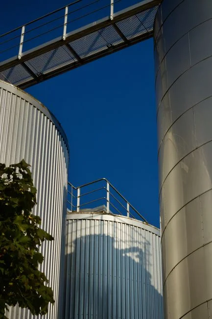
The thickener symbol on a PFD changes with the technology, and the wrong symbol on a drawing review is a common cause of procurement delays. Drawing the same five-block logic for three different technologies keeps the mass balance intact and lets the EPC reviewer trace each stream back to a unit operation. The technology is selected by feed source, available footprint, and downstream dewatering target, not by copying a vendor sketch.
A gravity thickener is drawn as a circular or rectangular vessel with a central feed well, a sludge blanket, a bottom hopper, and an underflow pump. The subnatant overflows a peripheral launder and returns upstream. Gravity thickening is normally matched to primary sludge where settleable solids dominate. A DAF thickener is drawn as an air-flotation cell with a saturator, a micro-bubble release zone, and a surface float scraper; the floated sludge is the "underflow" and the bottom water becomes the clarified stream. The geometry is inverted compared to a gravity unit, and the underflow arrow on the PFD points upward. A DAF thickener unit is normally matched to waste activated sludge where buoyancy rather than settling drives separation. A centrifuge thickener is drawn as a scroll or decanter symbol with a feed pipe, a polyelectrolyte injection point, and two discharge streams: a concentrate cake going to a downstream dewatering unit and a centrate returning upstream. The flow diagram is shorter but the discharge logic is identical.
The technology-to-feed mapping is the decision rule a designer writes into the PFD legend. Gravity maps to primary sludge, DAF maps to waste activated sludge, and centrifuge maps to space-constrained sites or high-solids digestion feed where a vessel footprint is not feasible. The same five blocks reappear in all three; the PFD logic is constant while the symbol is variable. The comparison below lets a designer pick the right block without re-drafting the upstream or downstream lines.
| Technology | Symbol on PFD | Typical feed | Underflow direction | Clarified stream |
|---|---|---|---|---|
| Gravity thickener | Circular/rectangular vessel, feed well, hopper, underflow pump | Primary sludge | Downward to hopper | Subnatant over peripheral launder |
| DAF thickener | Flotation cell, saturator, micro-bubble release, float scraper | Waste activated sludge | Upward to float scraper | Bottom water out of cell |
| Centrifuge thickener | Scroll/decanter with feed pipe and polyelectrolyte injection | Digester feed or space-constrained sites | Cake out of scroll | Centate return |
Reading Stream Labels, Symbols, and Control Loops on a 2026 PFD
The annotation layer of a PFD is where design reviews often face challenges. Three conventions are non-negotiable. First, stream arrows: arrowheads point in the direction of bulk flow, and the underflow arrow on a DAF diagram points upward because the floated sludge leaves over the top of the cell. A reader who expects a downward arrow will mis-route the underflow line to a non-existent bottom outlet. Second, instrumentation blocks: the PFD should carry at least a feed flow tag, a thickened-sludge flow or torque tag, and a clarified-stream turbidity tag. A discrete underflow control loop, as documented by Leonov and Sosnovskaya (2023, DOI 10.34660/inf.2023.80.57.008), should appear as a single block with a discrete on/off signal rather than a continuous PID loop; the P&ID carries the loop detail. Third, mass-balance flags: a PFD without a labelled recycle stream is incomplete, and the clarified-stream return mass balance must close before the diagram is approved. Where rising sludge in a downstream clarifier is suspected, the rising sludge troubleshooting guide covers the diagnostic chain a reviewer will follow back to the thickener recycle line.
Design Checklist Before Approving a Sludge Thickener PFD
An EPC reviewer or plant engineer can use the following checklist to evaluate any thickener PFD submitted for approval.
- Verify each block is shown: feed, thickener, polymer injection, underflow, clarified return, and downstream dewatering interface.
- Verify each technology-specific sizing parameter is on the diagram: for DAF, the 24–48 lb/ft²/day solids loading window and polymer dose line; for gravity, the surface overflow rate; for centrifuge, the G-force and differential speed.
- Verify the underflow is shown as a discrete control element, not a passive outlet, consistent with the discrete-control literature (Leonov & Sosnovskaya, 2023).
- Verify recycle closure: the clarified stream return must show where it re-enters the plant so total suspended solids loading is preserved; cross-check against the secondary clarifier design criteria for the receiving unit.
Frequently Asked Questions
What is the difference between a sludge thickener PFD and a P&ID?
A process flow diagram (PFD) shows mass and stream direction between unit operations: feed, thickener, polymer, underflow, clarified return, and downstream dewatering. A P&ID adds valves, instruments, and control loops, including the discrete underflow-discharge loop documented by Leonov and Sosnovskaya (2023, DOI 10.34660/inf.2023.80.57.008). The PFD is the mass-balance document; the P&ID is the control and mechanical document.
How do I size a DAF thickener on a 2026 PFD?
For waste activated sludge, the sizing variable is the solids loading rate, and the 2026 DAF thickener solids loading rate guide gives 24–48 lb/ft²/day with polymer conditioning. Compute the required air-to-solids ratio and saturator flow from the inlet TSS, then size the cell footprint from the loading rate. Polymer dose and mix energy are set on the chemical dosing P&ID, not the PFD.
What should I check first when comparing thickener supplier quotes?
Confirm that each supplier has drawn the same five blocks on their PFD and used the same sizing variable for the proposed technology. A quote based on a generic vendor sketch that omits the polymer injection block, the underflow discrete control tag, or the clarified-stream recycle line is not directly comparable to one that includes all five. Request the supplier's mass balance and the recycle closure point before pricing is finalised.
How long does delivery and commissioning take for a thickener system?
Lead time depends on the thickener technology, vessel fabrication, and the polymer dosing skid. Request a written delivery schedule that breaks the project into engineering submittal, vessel fabrication, skid fabrication, shipping, and commissioning milestones, and tie each milestone to a hold point in the PFD review. Lead time figures vary by region and supplier; obtain them in writing from each bidder before contract award.