

How Semiconductor Plants Near Bolingbrook Meet 2026 Pretreatment Limits
Semiconductor fabs in the Bolingbrook, Illinois area meet pretreatment limits through a layered approach: site-specific source control tied to EPA categorical pretreatment standards, combined with local limits enforced by the Metropolitan Water Reclamation District of Greater Chicago (MWRDGC) Sewage and Wastewater Ordinance. Operators generate up to 15 to 18 distinct wastewater grades, treating each stream—chemical mechanical planarization (CMP) slurry, hydrofluoric acid/buffered oxide etch (HF/BOE) rinses, arsenic-bearing rinses, isopropyl alcohol (IPA), copper-bearing plating rinses, and acid/alkali streams—with point-of-use or centralized treatment before blending. Common unit operations include fluoride and arsenic polishing, chemical precipitation, lamella clarification, dissolved air flotation for suspended solids, and chemical dosing for pH and flocculation, all verified by MWRD-mandated sampling and Significant Industrial User reporting.
Why Bolingbrook Fabs Face a Three-Layer Pretreatment Stack
Meeting industrial wastewater pretreatment limits involves navigating a regulatory framework that begins with federal categorical standards. The United States Environmental Protection Agency (EPA) mandates industrial pretreatment under the Clean Water Act to prevent pollutants from disrupting wastewater treatment processes (S3). For semiconductor manufacturing, this framework establishes categorical limits and pretreatment standards, which facilities must confirm against the current 40 CFR Part 437 semiconductor category.
The second layer consists of local limits set by the Metropolitan Water Reclamation District of Greater Chicago (MWRDGC). Sanitary sewer discharges from Bolingbrook flow into the MWRDGC system, which serves facilities like the Stickney Water Reclamation Plant. The MWRD Sewage and Wastewater Ordinance establishes binding local numeric limits and prohibited-pass-through rules that every fab must meet. Facilities must consult the current MWRD publication to confirm these exact General Conditions limits.
Finally, once a facility is designated as a Significant Industrial User (SIU), it negotiates a site-specific discharge permit. This permit specifies monitoring points, self-monitoring frequency, and reporting requirements. The fundamental purpose of pretreatment is to remove, reduce, or alter harmful pollutants at the source before they enter the sanitary sewer system. This protects worker safety, safeguards water resource recovery facilities, prevents the pass-through of harmful pollutants into receiving waters, and enables the safe reuse of biosolids (S3).
What Comes Out of a Fab: The Wastewater Streams That Drive Pretreatment Design
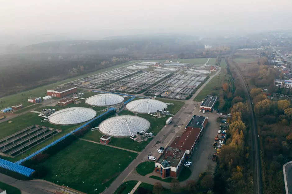
Semiconductor fabrication processes generate a diverse range of wastewater streams, with operators typically distinguishing between 15 to 18 distinct grades based on contamination levels and matrices (S5). This complexity necessitates segregated treatment strategies rather than a single, blended approach.
One critical stream is chemical mechanical planarization (CMP) slurry wastewater, which contains colloidal silica, ceria or alumina abrasives, various metals (including copper), and surfactants. DAS Environmental Experts (DAS EE) identifies CMP wastewater as a dedicated treatment target due to its unique composition (S2).
Hydrofluoric acid (HF) and buffered oxide etch (BOE) rinses carry significant fluoride concentrations. Additionally, arsenic can be a co-contaminant in certain etch and doping steps. DAS EE explicitly lists the treatment and polishing of wastewater containing both fluoride and arsenic as a standard service for the semiconductor industry (S2).
Isopropyl alcohol (IPA) and other volatile organic compounds (VOCs) are generated by solvent rinses and some waste-gas scrubbers. DAS EE treats IPA and other VOC-laden wastewater as a separable stream requiring specific handling (S2).
Plating and metallization rinses are sources of copper and other heavy metals, along with acids and alkalis. Resist stripping and developing effluents can also contribute to chemical oxygen demand (COD) and biochemical oxygen demand (BOD) loads. DAS EE offers solutions for both COD/BOD removal and heavy-metal removal as standard services (S2).
Beyond process-specific streams, cooling-tower blowdown and scrubber water also contribute meaningfully to the total fab wastewater volume. These streams have a different pollutant signature compared to process waters, and up to 40% of this water can be reused in cooling towers and scrubber machines (S5).
| Wastewater Stream Origin | Primary Pollutants | Key Treatment Drivers |
|---|---|---|
| Chemical Mechanical Planarization (CMP) | Colloidal silica/ceria/alumina, copper, other metals, surfactants | Suspended solids, metal precipitation |
| Hydrofluoric Acid / Buffered Oxide Etch (HF/BOE) Rinses | Fluoride | Fluoride precipitation/polishing |
| Arsenic-bearing Rinses | Arsenic | Arsenic precipitation/polishing |
| Isopropyl Alcohol (IPA) / VOC Rinses & Scrubber Condensate | IPA, other volatile organic compounds | VOC removal (air stripping, absorption) |
| Plating & Metallization Rinses | Copper, nickel, other heavy metals, acids, alkalis | Heavy metal precipitation, pH adjustment |
| Resist Stripping & Developing | COD, BOD, acids, alkalis | Organic load reduction, pH adjustment |
| Cooling Tower Blowdown & Scrubber Water | Dissolved solids, scale inhibitors, biocides, suspended solids | TDS reduction, suspended solids removal |
How Each Stream Is Treated Before It Reaches the Sanitary Sewer
Effective pretreatment for semiconductor wastewater streams begins with source segregation, as the diversity of contamination levels across 15 to 18 distinct grades (S5) makes a one-size-fits-all approach impractical. Pretreatment design involves segregated headers for CMP, HF/BOE, arsenic-bearing, IPA/VOC, and acid/alkali streams, each feeding its own dedicated treatment train. DAS Environmental Experts offers centralized, semi-centralized, and point-of-use architectures to accommodate these varied needs (S2).
For CMP wastewater, treatment steps include equalization, pH adjustment, and flocculation/coagulation, followed by dissolved air flotation (DAF) or lamella clarification to remove suspended solids, colloidal silica/abrasives, and associated metals. A HydropureWater DAF system is used for handling suspended solids and FOG-like loads in industrial pretreatment.
Fluoride and arsenic-containing streams undergo calcium- or alum-based coagulation/precipitation, followed by lamella or sedimentation clarification. DAS EE’s product line covers the treatment and polishing of fluoride- and arsenic-containing wastewater (S2). A HydropureWater lamella clarifier is designed for high-rate flocculation and inclined-plate separation, reducing chemical consumption.
Heavy-metal streams, such as those carrying copper or nickel, require pH adjustment to facilitate hydroxide precipitation, followed by lamella clarification. For facilities with stringent metal discharge limits, optional ion exchange or membrane polishing may be necessary. DAS EE lists heavy-metal and toxic-compound removal as a core offering (S2).
IPA and other VOCs are addressed through air stripping or dedicated scrubber/absorber systems. DAS EE integrates point-of-use waste-gas scrubbers with the subsequent wastewater treatment of the resulting condensate (S2).
For pH control and polishing of COD/BOD, equalization is a standard first step, followed by biological or chemical-physical polishing processes to reduce organic loads. DAS EE has over 15 years of experience building fab wastewater plants that utilize biological and chemical-physical processes to meet legal limits (S2).
A final polish involves multi-media filtration to reduce the silt density index (SDI), protecting downstream reverse osmosis (RO) or reuse membrane systems. A HydropureWater multi-media filter is sized to deliver RO-protective SDI, and the same treatment train can be integrated to protect internal reuse loops.
MWRD Sampling, Reporting, and What Triggers Enforcement
Significant Industrial Users (SIUs) discharging to the MWRD system must self-monitor and submit periodic compliance reports. The Clean Water Services model outlines an enforcement-response plan that ranges from a warning letter to an administrative penalty and potential orders to stop discharging for significant noncompliance (S3). This typical POTW model parallels MWRD’s approach to industrial user compliance.
Pretreatment focuses on removing, reducing, or altering harmful pollutants before they enter the sanitary sewer, rather than treating blended POTW influent (S3). This principle requires fab pretreatment design to prioritize segregated streams and dedicated treatment trains over single, end-of-pipe systems for mixed wastes.
Pretreatment programs reward facilities that implement recovery and reuse initiatives. Recovering byproducts, chemicals, and valuable metals at the source minimizes discharge, enables the production of cleaner biosolids, and facilitates treated wastewater reuse (S3). This logic drives investments in metal recovery and reclaimed water systems, with some facilities achieving up to a 99% water recycling rate (S5).
Noncompliance with pretreatment limits carries public implications. Regulators are mandated to report facility names and the specific type of significant noncompliance annually (S3). Consequently, a single discharge excursion can become a public-facing issue.
Pretreatment Equipment Checklist for a Bolingbrook Fab Project
Selecting pretreatment equipment for a Bolingbrook-area semiconductor fab involves specifying unit operations tailored to segregated wastewater streams and their specific pollutant profiles. A common starting point for various segregated streams is equalization and pH control, managed by a HydropureWater automatic chemical-dosing skid. These PLC-controlled systems inject coagulant, flocculant, and pH adjusters based on flow rates and characteristics of the individual streams.
For suspended solids and CMP slurry removal, a HydropureWater DAF system, available in capacities from 4 to 300 m³/h and utilizing micro-bubble flotation, is essential for removing colloidal particles and abrasives. This is paired with a HydropureWater lamella clarifier for high-rate separation of flocculated solids.
Fluoride, arsenic, and heavy metals precipitation trains feature a HydropureWater lamella clarifier, often with sludge recirculation to optimize coagulant consumption. The resulting metal-bearing sludge is dewatered using a HydropureWater plate-and-frame filter press, which covers filtration areas from 1 to 500 m².
For reclaim and reuse loops, a HydropureWater multi-media filter is critical for protecting downstream RO or advanced reuse skids by reducing SDI. This treated water can be fed to scrubbers, cooling towers, or further purified for ultra-pure water (UPW) makeup. Advanced facilities have achieved 99% recycle rates (S5).
When integrating these unit operations, modularity is a key consideration. DAS Environmental Experts emphasizes modular, prefabricated systems for fast installation and clear upgrade paths for existing plants (S2). This modular philosophy applies when specifying HydropureWater unit operations into a brownfield fab, facilitating efficient deployment and future scalability.
Frequently Asked Questions
What is the typical lead time for a custom semiconductor wastewater treatment system?
Lead times for custom semiconductor wastewater treatment systems vary significantly depending on complexity, size, and degree of prefabrication. DAS Environmental Experts emphasizes modular, prefabricated systems to facilitate faster installation (S2). To obtain an accurate lead time for a specific project, a buyer should provide detailed specifications, including flow rates, pollutant profiles, and desired discharge limits, and request a project timeline directly from the equipment supplier.
How do I determine the appropriate capacity for a dissolved air flotation (DAF) system for my fab’s CMP wastewater?
Determining the appropriate DAF capacity requires an assessment of your CMP wastewater stream’s peak and average flow rates, as well as the concentration and characteristics of suspended solids and colloidal abrasives. HydropureWater DAF systems are available in a range of capacities from 4 to 300 m³/h. An engineer should conduct a wastewater analysis and consult with a treatment system provider to size the DAF unit based on operational data and MWRD discharge requirements for suspended solids.