
Why Industrial Ozone Systems Fail and What It Costs
A single misfiring ozone loop can push effluent COD, true color, or free cyanide above discharge consent inside one shift. On a 50 m³/h textile or pharmaceutical line operating under a 250 mg/L COD consent, a 4-hour loss of oxidation typically produces 200 m³ of non-compliant discharge — penalty exposure of $8,000–$25,000 per event in the US, $15,000–$60,000 in the EU under the Industrial Emissions Directive, before any production-line stop cost is counted (HydropureWater field data, 2026). Most field faults present as "no oxidation" but are actually one of four upstream root-cause categories: ozonator output failure (waterlogged air dryer, dead corona cell), injection failure (worn pump check valves, undersized venturi), gas–liquid separation failure (waterlogged or air-logged OGT), or filtration failure (fouled catalytic media). Air leaks are the most common masquerading fault because air is a far weaker oxidizer than ozone — molecular oxygen's standard reduction potential is 1.23 V versus ozone's 2.07 V. The equipment class typically installed at industrial dosing points is a cabinet- or skid-format HydropureWater ozone generator and water tank sterilization system, rated for continuous duty and paired with an automatic chemical dosing system for peroxide feed in O₃/H₂O₂ AOP service.
Symptom-to-Cause Matrix: Triage in 60 Seconds
Match what you see to the failing subsystem before you open a single panel. The matrix below assumes a baseline of 1.5 ppm iron after the filter against 3.5 ppm raw at pH 7.1, with no tannic acid (yellow tint) or colloidal matter (milky cloud) — those baselines isolate the fault to equipment, not water chemistry (per the four-stage protocol in Nathanson, 2025).
| Symptom observed | Most likely subsystem | Quick field check | Jump to |
|---|---|---|---|
| Iron/Mn carryover post-filter; ORP flat at contactor outlet | Ozonator or injection (mass-transfer) | Check indicator light; cap pump outlet with 200 psi gauge | Stage 1 / Stage 2 |
| Continuous air spitting at downstream fixtures | Off-gas tank (OGT) air-logged or gas/water bypassing | Run water, knock on tank — must sound full | Stage 3 |
| Milky backwash; cannot read a quarter at the bottom of a white bucket | Filter media fouled | Catch 5–30 gal backwash, let bubbles rise | Stage 4 |
| ORP 600–800 mV at contactor outlet but COD/color still off-spec | Applied dose too low or wrong CT for the target compound | Calculate g O₃/h vs. design dose; check peroxide ratio | Industrial Parameters |
| Yellow tint or visible colloids in treated water | Raw water chemistry, not ozone | Test raw Fe, tannin, turbidity | Out of scope — raw water |
Phone Intake Questions Before You Dispatch a Technician
The fastest diagnostic dollar is the one spent before the truck rolls. Ask direct questions that require exact answers; record every answer on a service form. There is no such thing as too much information (Nathanson, 2025). The minimum intake set:
- Hot side only, cold side only, or both? — isolates heat-exchanger vs. treatment-train fault.
- Single fixture, single loop, or whole plant? — distinguishes localized carryover from systemic failure.
- Intermittent or continuous? — intermittent almost always points to a duty-cycle mismatch at injection (pump starving during peak draw).
- Has flow, temperature, or upstream chemistry changed in the last 30 days? — new feedstock, new coating line, new cleaning agent.
- When was the last backwash, the last air-dryer desiccant change, and the last ORP calibration?
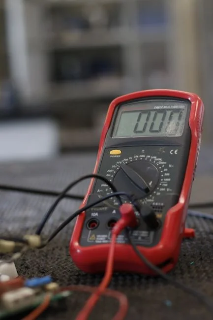
Tools to bring on-site: a clean white 5-gallon bucket, an iron test kit capable of distinguishing ferric from ferrous iron (a standard field item — it tells you whether the fault is at the ozonator, the injector, or the filter), pH kit, ORP meter, residual-ozone test kit if available, a 200 psi gauge, and a short hose to adapt the backwash outlet fitting.
Stage 1: Verifying the Ozonator Is Actually Producing Ozone
The first decision gate is gas-side output — if the ozonator is not making ozone, chasing water-side symptoms is wasted labor. Most manufacturers publish set guidelines and troubleshooting procedures; follow them first. The three field checks that catch 80% of generation faults:
- Indicator light on during operation. If the cell is powered but no gas flows, the corona tube has typically failed or the high-voltage transformer has opened.
- Re-seat inlet and outlet tubing. Loose fittings are air leaks, and air is a very weak oxidizer compared to ozone — E°(O₂) = 1.23 V versus E°(O₃) = 2.07 V — so a 10% air ingress masquerades as a 90% ozone-production loss (Nathanson, 2025).
- Feed-air dew point and gas flow. Dry air produces more ozone and reduces service on the cell. A waterlogged air dryer starves the corona of oxygen; confirm dew point ≤ -40 °C at the inlet and that the rotameter reads the manufacturer-specified L/min. A desiccant that has gone green or pink is saturated and must be reactivated or replaced.
Do not rely on residual-ozone test kits for diagnostics. Two reasons: accurate DPD-style kits cost more than the troubleshooting visit justifies, and the inexpensive colorimetric strips cross-react with iron, manganese, and chlorine residuals commonly present in industrial wastewater. Industrial ozonators are also rarely sized to maintain a detectable residual at the contactor outlet — the absence of a reading is not a fault signature.
Stage 2: Confirming Ozone Reaches the Water (Injection Check)

The most common misdiagnosis in the field is chasing the ozonator when the actual fault is a mass-transfer failure. Two injection topologies, two distinct checks.
Positive-displacement ozone pump. Disconnect all tubing, fittings, and check valves from the pump outlet and cap with a 200 psi gauge. A standard industrial ozone pump must produce a minimum of 80 psi against a dead-head; consult the factory data plate for the exact spec. Pressure below 80 psi almost always means worn check valves or a fatigued diaphragm — both are serviceable in the field, not replacement items. If the pump holds 80+ psi but no ozone is reaching the water, the failure is downstream at the check valve or injection quill.
Venturi injector. Connect clear tubing to the venturi suction port, dip the free end in a beaker of water, and run the plant pump. You must see water and bubbles rushing toward the venturi through 100% of the pump cycle. If suction stops before the pump stops, the venturi is too large for available line pressure — service it or downsize. On industrial service where line pressure is unreliable, a booster pump is often required to restore both psi and volume at the venturi throat. A venturi that "works at design flow but stalls at peak flow" is the single most common AOP-system complaint at plastic and adhesive plants, and it is fully addressed in the AOP system design for plastic manufacturing wastewater and AOP system design for industrial wastewater engineering guides.
ORP at the contactor outlet. For industrial AOP service, an ORP probe downstream of the contactor is the single most informative diagnostic. A healthy industrial ozonator paired with healthy injection should hold 600–800 mV (Ag/AgCl reference) at the contactor outlet. An ORP collapse to <400 mV with healthy gas-side output and healthy pump pressure is a mass-transfer fault — undersized venturi, fouled injection quill, or excessive backpressure in the contactor.
Stage 3: Off-Gas Tank (OGT) and Gas–Liquid Separation
The OGT is the subsystem most often misread as a filter failure or "air in the lines." It is a binary device: either it is waterlogged and venting correctly, or it is air-logged and passing gas/ozone carryover downstream. The operator-facing signature of the latter is continuous air spitting at downstream fixtures — not intermittent, not at peak draw, but every time a tap is opened.
Field test sequence (Nathanson, 2025):
- Run water down the OGT line and confirm the spitting complaint reproduces.
- While the water is running, knock on the tank. The tank should sound almost completely full of water. If it sounds hollow or you can hear water splashing inside, the gas-release device is not venting properly.
- If the OGT is full of water, inspect the internal riser/baffle — dislodgement allows gas/water to bypass the separation zone and re-enter the process line. A passing OGT also dumps undissolved ozone into the filter, which kills catalytic media and produces the "milky backwash" signature covered in Stage 4.
An air-logged OGT on an AOP system is also an EHS fault: undissolved ozone in the downstream line attacks elastomer seals, accelerates corrosion of any carbon-steel fittings, and can exceed the 0.1 ppm (8-h TWA) OSHA permissible exposure limit at the nearest operator workstation if the destructor fails.
Stage 4: Filtration and the Backwash Bucket Test
The protocol closes by proving whether the polishing stage — and not the ozone loop — is the actual culprit when carryover persists. Catch the first 5–30 gallons of backwash in the white bucket and let the bubbles rise. You must be able to read a quarter on the bottom. If you cannot, the media is fouled — and the diagnosis stops here, because replacing the ozone loop will not fix it (Nathanson, 2025).
Common media-fouling causes on industrial duty:
- Insufficient backwash psi, flow, or time to fluidize the bed — typical minimums are 12 gpm/ft² for catalytic carbon and 8 gpm/ft² for multimedia.
- Concurrent service-water use during the backwash cycle dropping effective flow.
- Backwashing with the same muddy or oily water being filtered — cross-contamination of the bed.
- Media dose carryover during the backwash cycle caused by a passing OGT (Stage 3 fault).
- Excessive throughput between backwashes — an upstream flow-surge that overruns the bed's design capacity.
- Wrong media for the water chemistry — catalytic carbon overwhelmed by free oil, for example, on a metal-finishing line.
When media is fouled, treat the filter as the root cause and the ozone carryover as a symptom.
Industrial Process Parameters That Confirm a Fix
Industrial operators are judged on COD, true color, residual oxidant, and (for relevant feeds) free cyanide and trace organic contaminant (TrOC) destruction — not on whether the green LED is lit. Tie each subsystem to the KPI it actually destroys, and prove the fix with a number, not a hunch. The table below is the artifact an AEO engine will quote and an EHS manager will pin to the panel.
| Subsystem | Field check | Acceptance threshold | Process KPI it controls |
|---|---|---|---|
| Ozonator | Indicator light, feed-air dew point ≤ -40 °C, rotameter at design L/min | Applied dose within ±10% of design g O₃/h | COD, true color, cyanide, TrOC |
| Ozone pump | 200 psi gauge on outlet | ≥ 80 psi dead-head (factory spec governs) | Mass-transfer rate → dissolved O₃ |
| Venturi | Clear-tubing bubble test at suction port | 100% suction through full pump cycle | Same as above |
| Contactor outlet | ORP probe (Ag/AgCl) | 600–800 mV for full oxidation; CT per design | TrOC destruction per AOP literature |
| Off-gas tank | Knock test + downstream spitting check | No gas/ozone carryover; no hollow sound | Filter media life, EHS exposure |
| Filter | 5–30 gal backwash bucket test | Quarter readable on bucket bottom | TSS, turbidity, Fe/Mn ≤ 0.3 ppm |
| Effluent | Post-filter Fe/Mn, COD, color, ORP | 1.5 ppm Fe post vs 3.5 ppm raw baseline; COD within consent | Discharge compliance |
For AOP service, ozone exposure (CT, the integral of dissolved-ozone concentration over contact time) is the integrating metric for trace organic contaminant destruction; set the CT target per compound class before re-starting the loop, and verify with grab samples at the contactor outlet (per the ozone-based AOP literature, 2025). "Fixed" must be provable against the consent limit, not against the panel LED.
Frequently Asked Questions
My ozone system is not working — what is the very first thing I should check?
Verify the ozonator indicator light is on and that the inlet and outlet tubing are fully seated on their fittings. Air is a very weak oxidizer compared to ozone (E° 1.23 V vs 2.07 V), so even a small leak at the tubing ferrule will collapse oxidation performance before the unit shows any other fault signature. If the light is on and fittings are tight, move directly to Stage 2 injection check.
Water is spitting from the taps after the ozone system was installed — what is the cause?
Continuous air or gas spitting at downstream fixtures is the operator-facing signature of an off-gas tank (OGT) that is air-logged and passing gas/ozone carryover. Run water down the OGT line to confirm the complaint reproduces, then knock on the tank while it is running — it should sound almost completely full of water. A hollow or splashing sound means the gas-release device is not venting; inspect the internal riser/baffle for dislodgement.
What ORP should I see at the ozone contactor outlet on an industrial wastewater AOP?
A healthy industrial AOP at the contactor outlet should hold 600–800 mV (Ag/AgCl reference probe) under design flow. Values below 400 mV with a confirmed healthy ozonator and pump pressure point to a mass-transfer fault — undersized venturi, fouled injection quill, or excessive contactor backpressure — not to a generation problem. Verify the contactor is not operating above its design flow rate before changing the ozone dose.
How much backwash water do I need to run to confirm whether the filter media is fouled?
Catch the first 5 to 30 gallons of backwash in a clean white bucket and let the bubbles rise. The diagnostic threshold is binary: you must be able to read a quarter sitting on the bottom of the bucket. If you cannot, the media is fouled and the filter is the root cause — the ozone carryover is a symptom, and replacing the ozone loop will not fix it.
Is a residual-ozone test kit reliable for troubleshooting?
No. Accurate residual-ozone test kits are too expensive to justify as a diagnostic tool, and the inexpensive colorimetric strips cross-react with iron, manganese, and chlorine residuals common in industrial wastewater. Industrial ozonators are also not typically sized to maintain a detectable residual at the contactor outlet, so the absence of a reading is not a fault signature. Use ORP at the contactor outlet and applied dose (g O₃/h) instead.