A secondary clarifier maintenance program covers daily sludge-blanket checks, monthly weir cleaning, quarterly drive lubrication, and annual bearing wear measurement. Keep main drive bearing clearance below 0.010 inches and collector-chain elongation at or under 2% of original length to limit misalignment, short-circuiting, and unplanned downtime.
Why Secondary Clarifier Maintenance Prevents System Failure
Secondary clarifiers remove 70–90% of settleable solids in activated sludge trains and form the last barrier before discharge. Neglected drives, weirs, or scrapers raise effluent TSS within hours. According to US EPA guidance, 60% of recent NPDES significant non-compliance violations occurred at small facilities. EPA 40 CFR Part 133 still requires 30-day TSS ≤30 mg/L and ≥85% removal.
Hydraulic overload and sludge bulking remain the two failure modes most often tied to neglected upkeep. US EPA compliance tips for small mechanical WWTPs list clarifiers out of service and solids loss from clarifiers among common noncompliance causes. Unleveled or fouled effluent weirs create short-circuiting, so flow races through narrow zones and carries floc over the weir. Compromised rake arms or suction headers leave sludge in dead zones long enough to go septic and rise, raising TSS and drive torque at the same time.
Inspected and lubricated units commonly run 25 to 30 years. Neglected drives often need major overhaul or full replacement within about a decade. Tracking bearing clearance, chain stretch, and torque trends lets crews schedule work in low-flow windows instead of during peak hydraulic events.
Daily Maintenance Tasks for Continuous Operation
Routine sludge-blanket checks are the first daily control point. In most conventional activated sludge layouts, operators hold the blanket between 1 and 2 feet (0.3–0.6 m) using a sludge judge or ultrasonic interface sensor at the same time and location each day. A rising blanket without higher influent flow points to Return Activated Sludge (RAS) shortfall or scraper problems. Checking that upstream mechanical bar screens are clear reduces debris that can foul clarifier piping and headers.
Inspect the scum system every 8 to 12 hours where Fats, Oils, and Grease (FOG) loads are high. Confirm full skimmer contact and a clear scum trough. Blocked scum lines form mats that favor filamentous organisms such as Nocardia and prolong foaming. Food and beverage plants usually need more frequent grease cleaning so deposits do not harden on moving parts.
Log drive motor RPM and listen for new vibration or noise each shift. Handheld vibration readings at the motor and gearbox establish a baseline; rising vibration often signals misalignment or early bearing wear. A multi-day climb in torque usually means sludge is building on rake arms from slow withdrawal or an overly thick blanket, and early action can avert a high-torque trip.
Weekly and Monthly Inspections to Prevent Downtime

Clean effluent weirs monthly so flow distributes evenly around the tank periphery. Thin algae or slime dams create local high-velocity notches that pull floc over the weir and threaten TSS compliance. Use stiff nylon brushes on V-notch weirs and baffles; in warm climates, bi-weekly cleaning may be needed in summer. Re-level weir plates when flow is uneven, holding elevation within ±0.25 inches of design.
Check sludge withdrawal pumps weekly for cavitation or wear. A “marbles in a blender” sound often means a partial suction blockage or operation too far right on the pump curve. If flow at a given RPM falls more than 15% from the baseline curve, inspect the impeller for wear or debris. The same solids-removal discipline applies in maintenance best practices for DAF clarifiers in industrial settings, where removal efficiency is the primary KPI.
On chain-and-flight collectors, verify chain tension weekly. Keep elongation at or below 2% of original length; loose chain can jump sprockets and pile flights on the floor. Flights must track square across the tank floor. A tilted flight usually means uneven chain stretch or a failed wear shoe—replace shoes before they cut into the flight structure.
Quarterly Lubrication and Drive System Care
Lubricate industrial clarifier drive gearboxes every 500 operating hours or quarterly, whichever comes first, to limit friction heat damage. For open gears and large-diameter bearings, EP2 lithium-based grease is commonly specified for water resistance and extreme-pressure load. Avoid over-greasing: excess grease can breach seals and trap moisture. Follow the manufacturer’s volume for each grease point.
Bleed condensate from gearbox drains on the same quarterly cycle in humid plants or sites with large day–night temperature swings. Water that settles in the oil reservoir emulsifies lubricant and cuts film strength. Desiccant breathers reduce moisture ingress. Replace milky or cloudy oil immediately. Where settleability is weak, plants often add automated flocculant dosing to improve sludge settleability, which lowers rake torque demand.
Function-test torque protection each quarter. Confirm shear pins are the specified alloy—not a hard substitute bolt—and that electronic limiters still trip. Calibrate 4–20 mA torque signals so the PLC reads true load. A failed trip during bulking can twist a rake shaft or destroy a gearbox and cost tens of thousands of dollars in parts and labor.
Annual Overhauls and Wear Measurement Protocols
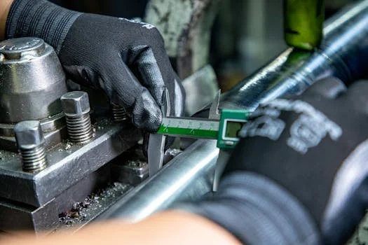
Measure main drive bearing clearance annually with a feeler gauge (gap check). Clearance above 0.010 inches indicates the bearing is near end of life and should be replaced at the next planned outage. Ignoring the gap check can let the gear climb its housing, wear teeth unevenly, and seize the drive. The same quantitative tracking mindset supports long-term maintenance strategies for downstream sludge handling.
During the drained annual outage, inspect steel hoppers for corrosion pitting deeper than 1/8 inch; clean to white metal and rebuild with high-build epoxy. On concrete tanks, look for spalling or exposed rebar at the waterline where freeze–thaw and chemical attack concentrate. Replace torn or worn neoprene squeegees so sludge still moves to the center hopper instead of forming dead zones.
Recalibrate sludge-level sensors, flow meters, and effluent turbidimeters each year. Compare ultrasonic blanket readings to a manual sludge-judge measurement; adjust or clean the transducer if error exceeds 5%. Accurate instruments keep solids loading rate and surface overflow rate inside design envelopes.
| Component | Inspection Point | Failure Threshold | Action Required |
|---|---|---|---|
| Main Drive Bearing | Feeler Gauge Gap | > 0.010 inches | Replace bearing assembly |
| Collector Chain | 10-Link Elongation | > 2% of original | Replace chain and sprockets |
| Sludge Hopper | Corrosion Pitting | > 1/8 inch depth | Sandblast and epoxy repair |
| Effluent Weir | Level Tolerance | ± 0.25 inches | Re-level weir plates |
Maintenance Parameter Table: Frequencies, Tolerances & Tools
Quantitative wear limits turn clarifier care from reactive repair into scheduled predictive work. The table below consolidates frequencies and tolerances used with secondary clarifiers against EPA 40 CFR Part 133 TSS expectations (30-day average ≤30 mg/L and ≥85% removal under §133.102). Meeting these mechanical limits supports consistent TSS performance in industrial and municipal activated sludge plants.
| Task | Frequency | Acceptable Tolerance | Required Tools | Reference Standard |
|---|---|---|---|---|
| Check Sludge Blanket | Daily | 1.0 – 2.0 ft depth | Sludge Judge / Ultrasonic | EPA Design Guidelines |
| Clean Effluent Weirs | Monthly | No visible biofilm | Nylon brush / Pressure wash | EPA 40 CFR Part 133 |
| Drive Lubrication | Quarterly | 500 operating hours | Grease gun (EP2 lithium) | Manufacturer data |
| Chain Tension Check | Weekly | ≤ 2% elongation | Tape / elongation gauge | Manufacturer data |
| Bearing Gap Check | Annual | ≤ 0.010 inches | Feeler gauge | Manufacturer data |
| Torque Protection Test | Quarterly | Trip verified | Shear pin / 4–20 mA calibrator | Manufacturer data |
How Do You Select a Clarifier for Industrial Wastewater?
Clarifier selection for industrial wastewater starts with solids type, floatability, and peak hydraulic factor—not tank diameter alone. Choose primary clarification when grit and settleable TSS dominate raw influent; choose secondary clarification after biological treatment when the goal is biomass capture and effluent TSS control under 40 CFR Part 133-style limits. Prefer a Dissolved Air Flotation (DAF) System when FOG, emulsified oil, or low-density floc will not settle reliably in a gravity clarifier. Lamella (inclined-plate) packs raise projected settling area in a smaller footprint when land is constrained and solids are discrete and settleable.
Record design surface overflow rate in m³/m²·d (or gpd/ft²), solids loading rate in kg/m²·h, and peak-to-average flow ratio before locking geometry. Industrial plants with shock loads need surge volume or equalization upstream so the secondary clarifier is not sized only on average day flow. Match sludge withdrawal method (scraper, suction header, or chain-and-flight) to expected sludge volume index and hopper geometry.
Primary vs Secondary Clarifier Design Criteria
Primary clarifiers remove settleable solids and FOG ahead of biology; secondary clarifiers polish mixed liquor after aeration or anoxic zones. Primary units are commonly sized on surface overflow rate for raw TSS, while secondary units must also satisfy solids loading from mixed liquor suspended solids (MLSS) and RAS strategy. Where oils and fine solids dominate, a Dissolved Air Flotation (DAF) System often outperforms gravity secondary settling because microbubbles float light floc instead of relying on discrete settling.
Use gravity secondary clarification when floc settles well at the plant’s MLSS and temperature range. Use lamella modules when you need more effective settling area without expanding the tank shell. Keep maintenance access for weirs, drives, and collectors in the layout—selection criteria that ignore service clearances raise lifecycle cost even when hydraulic numbers look correct.
Who This Is For and Next Step
This protocol fits plant engineers, chief operators, and EPC teams running circular or rectangular secondary clarifiers on activated sludge or industrial biological trains. Look elsewhere if your solids are almost entirely floatable FOG with negligible settleable biomass—then prioritize flotation hardware and its service plan first. Before buying parts or scheduling a drained outage, capture seven baseline items: blanket depth trend, weir level survey, drive torque log, vibration baseline, chain elongation, bearing gap, and sensor calibration date. HydroPureWater can review those readings against your RAS and effluent TSS targets when you need a second process check.
Frequently Asked Questions
How often should secondary clarifier weirs be cleaned?
Clean effluent weirs at least monthly, and every two weeks in warm months when algae growth is rapid. Even thin biofilm creates damming at V-notches, which raises local velocity and pulls floc into the effluent launder. Nylon brushes or controlled pressure washing restore even overflow. After cleaning, confirm water height is within ±0.25 inches across all notches before returning the unit to normal duty.
What sludge blanket depth should operators maintain?
Most conventional activated sludge secondary clarifiers target a 1.0–2.0 ft (0.3–0.6 m) blanket at a fixed daily sample point. Deeper blankets without higher influent flow usually mean RAS rate is too low or scrapers are not moving sludge. Shallower blankets can starve RAS solids and destabilize the aeration inventory. Measure with a sludge judge or calibrated ultrasonic sensor and trend the reading with flow and torque.
When should a plant choose DAF instead of a secondary clarifier?
Choose flotation when FOG, emulsified oil, or low-density biological floc will not settle at the available surface overflow rate. Gravity secondary clarifiers excel at capturing settleable mixed-liquor floc after biological treatment. A Dissolved Air Flotation (DAF) System uses pressurized recycle and microbubbles to float light solids and often pairs with chemical conditioning. Many industrial sites run both: biology plus secondary settling for biomass, and flotation for oily sidestreams.
What bearing clearance requires drive bearing replacement?
Replace the main drive bearing assembly when feeler-gauge clearance exceeds 0.010 inches during the annual gap check. Clearance beyond that threshold raises misalignment risk and uneven gear wear. Schedule replacement in a planned drained outage rather than after a seizure. Record the gap, lubricant condition, and torque history so the next overhaul interval is data-based.
Which EPA rule sets secondary clarifier effluent TSS expectations?
EPA 40 CFR Part 133 sets secondary treatment floors that many NPDES permits mirror for municipal plants: 30-day average TSS ≤30 mg/L, 7-day average ≤45 mg/L, and 30-day average percent removal ≥85%. Industrial direct dischargers follow category-specific effluent guidelines, but poor clarifier upkeep still drives TSS and BOD excursions. EPA also flags clarifiers out of service and solids loss from clarifiers as recurring noncompliance causes at small mechanical plants.