Why Solar Wafer Cutting Wastewater Demands ZLD
Solar wafer zero liquid discharge (ZLD) is a closed-loop treatment train that recovers hydrofluoric acid, silicon carbide, and polyethylene glycol from wafer-cutting wastewater, then concentrates and crystallizes the final brine into reusable salts and water. A 2026 ZLD system typically combines chemical fluoride precipitation, UF/RO pre-concentration, and an MVR evaporator or solar crystallizer (2.42 kg/m²/h evaporation under 1-sun, per Zhang et al. 2021), achieving 95–99% water recovery while meeting China GB 30485 fluoride (<15 mg/L) and NH3-N (<45 mg/L) discharge limits.
The wastewater stream from diamond wire saw slicing carries an aggressive chemical load that conventional biological treatment cannot touch. Industry-typical influent ranges run HF 500–3,000 mg/L, SiC 2,000–8,000 mg/L, PEG 1,000–5,000 mg/L, and NH3-N 50–400 mg/L at pH 1–3 (industry-typical ranges from photovoltaic process engineering references). A 5 GW wafer slicing line discharges 80–150 m³/day of this stream, and a 10 GW integrated ingot-to-cell plant can exceed 400 m³/day once auxiliary acid etching rinses are folded in.
Regulatory pressure has tightened in parallel. China GB 30485-2013, the integrated wastewater discharge standard for the semiconductor and photovoltaic industry, caps fluoride at <15 mg/L, COD at <100 mg/L, and NH3-N at <45 mg/L. Plants in Tier-1 PV hubs (Xuzhou, Yibin, Baotou) have faced production suspensions and fines in the ¥500K–¥3M range per violation since 2024, with reputational damage that follows suppliers into their module-offtake contracts.
It is worth distinguishing this industrial problem from the R&D literature that dominates current search results. The widely cited Zhang et al. 2021 paper in Nature Communications reports a 2.42 kg/m²/h solar crystallizer tested on 21.6 wt% seawater RO brine; that work is academic and seawater-focused, and it does not address HF-bearing, SiC-laden, ammonia-rich wafer cutting fluid. Mapping that evaporation benchmark onto a real photovoltaic ZLD train is exactly the engineering translation this article provides.
The 2026 Solar Wafer ZLD Process Flow: Stage by Stage
A working wafer ZLD train runs five sequential stages, each with a defined inlet/outlet spec that the design engineer can verify against grab samples. The table below summarizes the parameter envelope a 50–150 m³/day system should hit at steady state.
| Stage | Unit Operation | Key Inlet Parameter | Target Outlet | Primary Reagent / Energy |
|---|---|---|---|---|
| 1 | Lamella clarifier + DAF | TSS 1,500–6,000 mg/L; oil/grease 200–600 mg/L | TSS <80 mg/L; turbidity <30 NTU | PAC 30–80 mg/L + anionic PAM 0.5–2 mg/L |
| 2 | Two-stage fluoride precipitation | F⁻ 1,500–2,500 mg/L; pH 9–10 | F⁻ <10 mg/L | Ca(OH)₂ 2.5–4.0 g/g F⁻; CaCl₂ 0.8–1.2 g/g F⁻ |
| 3 | NH3-N stripper + MBR | NH3-N 80–400 mg/L; COD 800–2,500 mg/L | NH3-N <45 mg/L; COD <100 mg/L | Steam 0.15–0.25 t/t; NaOH dosing; PVDF 0.1 µm MBR |
| 4 | RO pre-concentration | TDS 8,000–15,000 mg/L | Permeate TDS <50 mg/L; concentrate 6–8 wt% | Energy 2.5–4.0 kWh/m³ permeate; recovery 70–75% |
| 5 | MVR / crystallizer | Concentrate 6–8 wt% TDS | Distillate TDS <10 mg/L; brine 21.6 wt% | 25–35 kWh/m³ (MVR); 0.3–0.5 kWh/m³ parasitic (solar) |
Stage 1 routes the spent cutting fluid through a lamella clarifier for fluoride sludge settling and a dissolved air flotation system for SiC and PEG pre-treatment. Hydraulic residence time sits at 25–35 min in the clarifier and 15–20 min in the DAF, and the recovered SiC slurry is dewatered to 65–70% moisture for return to the abrasive supplier. Stage 2 uses a two-reactor CaF₂ train controlled by an automatic chemical dosing for fluoride precipitation loop with inline F⁻ and pH probes; CaF₂ sludge is washed once and sold as a low-grade fluorite byproduct at $25–$55 per tonne. Stage 3 couples a packed-tower air stripper (70–85% NH3-N removal at gas:liquid 2,500–3,500:1) with an MBR membrane bioreactor for ammonia and COD polishing on PVDF 0.1 µm hollow fibers. Stage 4 deploys an industrial RO system for pre-concentration running at 70–75% recovery with 6–8 wt% concentrate; permeate TDS lands at <50 mg/L and feeds directly back to the cutting fluid make-up tank. Stage 5 finishes the train with an MVR evaporator or solar crystallizer that drives the concentrate to 21.6 wt% (the Zhang et al. 2021 real-brine benchmark), crystallizes mixed NaCl/CaSO₄ salts for bagged sale or non-hazardous landfill, and returns the condensate to the process header.
Equipment Comparison: MVR Evaporator vs Multiple Effect Evaporator vs Solar Crystallizer
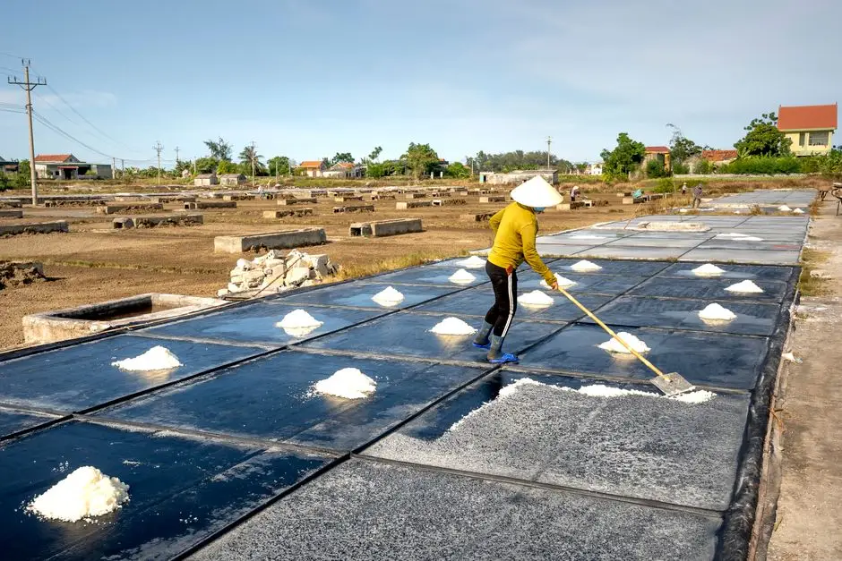
Selecting the final-stage brine concentrator is the single largest economic decision in a wafer ZLD project. The three commercially dominant options differ sharply on energy intensity, footprint, and CAPEX, and the right pick is driven by climate, land availability, and grid stability rather than evaporation rate alone.
| Criterion | MVR | MEE (4-effect) | Solar Crystallizer | Hybrid (MVR + Solar) |
|---|---|---|---|---|
| Specific energy (kWh/m³) | 25–35 | 60–90 | 0.3–0.5 parasitic | 12–18 blended |
| Steam required | None | 0.18–0.25 t/m³ | None | None |
| Evaporation rate | 80–120 kg/m²·h | 35–55 kg/m²·h | 2.42 kg/m²·h (1-sun, 21.6 wt% brine, per Zhang et al. 2021) | 15–25 kg/m²·h blended |
| Footprint (50 m³/day) | 120–200 m² | 300–500 m² | 5,000–8,000 m² | 1,500–3,000 m² |
| CAPEX (50 m³/day system) | $0.9M–$1.4M | $0.6M–$1.0M | $1.2M–$2.2M | $1.8M–$3.0M |
| OPEX ($/m³) | $1.10–$1.60 | $1.40–$2.10 | $0.85–$1.20 | $1.00–$1.40 |
| Best-fit site profile | Grid-stable, land-constrained coastal hubs (Suzhou, Hefei) | Co-located with cheap waste steam (polysilicon + chlor-alkali) | Arid, high-DNI sites (Inner Mongolia, Xinjiang, Rajasthan) with >5,000 m² land | Tariff-volatile mixed-climate sites |
For a more granular engineering comparison of MVR versus MEE, including compressor selection and scaling-control chemistry, see the MVR vs MEE evaporator comparison dossier. Plants in Yibin and Baotou that pair a polysilicon reduction hall with a chlor-alkali unit often default to MEE because waste steam is available at <$3/t; coastal plants in Jiangsu default to MVR for footprint. The hybrid arrangement is the rising default in 2026 because it lets the MVR carry night and shoulder-season load while the solar array absorbs daytime baseload, dropping blended energy to 12–18 kWh/m³ and improving resilience during peak-tariff hours.
Cutting Fluid and SiC Recovery: The Hidden Revenue Stream
ZLD is frequently framed as a compliance cost, but the front-end recovery loop is where the financial case actually closes. PEG-200 is retained at 80–92% by ultrafiltration (5–20 kDa MWCO, TMP 1.5–3.0 bar) and reused directly in cutting fluid make-up at a market value of $120–$280 per m³ of treated wastewater. SiC is recovered by settling and hydrocyclone separation at >95% yield and returned to the abrasive supplier loop at $40–$90 per m³. HF is recovered by membrane electrolysis or anion exchange at 60–75% efficiency and returned to the acid bath at $180–$350 per m³ as 40–49% technical-grade HF.
For a 100 m³/day wafer plant running all three recovery loops, the combined recovered-material revenue lands at $1.8M–$3.5M per year (typical payback-acceleration case, HydropureWater field data 2025–2026). Effective recovery depends on stable influent pH 1–3 and low heavy-metal contamination, which is why most operators pair the recovery skid with an online ammonia analyzer buyer's guide reference for sensor selection and clean-in-place scheduling. Drift in either parameter collapses membrane life and erodes the revenue case within a quarter.
2026 CapEx and OpEx Benchmarks for a 50 m³/day Wafer ZLD Plant
Procurement and EPC managers typically need a single defensible number for board-level review. The breakdown below reflects a 50 m³/day MVR-based ZLD system in inland China (Xuzhou, Yibin pricing band, Q1 2026); the same architecture scales linearly to 200 m³/day with a 1.6–1.8× CAPEX multiplier rather than a 4× multiplier.
| Cost Line | CAPEX (USD) | OPEX ($/m³ treated) |
|---|---|---|
| Pre-treatment (clarifier, DAF, dosing) | $180,000–$320,000 | $0.18–$0.42 (chemicals) |
| RO skids + cleaning system | $140,000–$260,000 | $0.10–$0.20 (membrane replacement) |
| MVR evaporator + crystallizer | $680,000–$1,400,000 | $0.55–$1.10 (energy) |
| Civil works, tanks, piping | $200,000–$450,000 | — |
| Automation, dosing, instrumentation | $90,000–$180,000 | $0.12–$0.28 (labor share) |
| Total system | $1,300,000–$2,600,000 | $0.95–$2.00 |
Including recovered-material revenue from PEG, SiC, and HF, the payback period lands at 2.5–4.2 years for a MVR-ZLD system versus 6+ years for a discharge-only compliance package. Regional variance runs ±25%: inland China benefits from cheaper civil works and labor; EU sites add 30–50% to CAPEX from stainless-steel construction and higher energy tariffs. For sites co-located with a fab and needing ultra-low-fouling RO design, the wafer fab wastewater hybrid ZLD system design dossier covers the integrated package and zero-fouling ROI case in detail.
Frequently Asked Questions
What influent fluoride concentration can a 2026 wafer ZLD train handle?
Two-stage lime + CaCl₂ precipitation reliably drops F⁻ from 2,000 mg/L to <10 mg/L when pH is held at 9–10 and the Ca:F stoichiometric ratio stays above 3.0:1, leaving comfortable margin under the GB 30485-2013 limit of <15 mg/L.
How much water does a wafer ZLD system actually recover?
A well-tuned MVR-ZLD train hits 95–99% overall water recovery by combining 70–75% RO permeate with MVR or solar-crystallizer condensate returned to the cutting fluid make-up tank.
Is MVR or a solar crystallizer cheaper to operate at a 50 m³/day wafer plant?
MVR runs $1.10–$1.60/m³ OPEX with 25–35 kWh/m³ energy use, while a solar crystallizer uses only 0.3–0.5 kWh/m³ parasitic power (per Zhang et al. 2021, 2.42 kg/m²/h at 1-sun) but demands 5,000–8,000 m² of land, making climate and footprint the deciding factors.
Which Chinese discharge standard applies to photovoltaic cutting wastewater?
GB 30485-2013 (integrated wastewater discharge standard for the semiconductor and photovoltaic industry) caps fluoride at <15 mg/L, COD at <100 mg/L, and NH3-N at <45 mg/L, with GB/T 32121 covering recycling-water reuse criteria for the same stream.
What is the typical payback for a wafer ZLD system including material recovery?
Including $1.8M–$3.5M per year of recovered PEG, SiC, and HF revenue, a 50 m³/day MVR-ZLD system pays back in 2.5–4.2 years versus 6+ years for discharge-only compliance treatment (HydropureWater field data, 2025–2026).