Why Ternary Precursor Wastewater Needs a Dedicated Process
NCM/NCA cathode precursor mother liquor is not a generic metal-bearing wastewater — its ionic matrix, sulfate background, and ammonia-nitrogen load make single-metal hydroxide precipitation rules unreliable. A typical co-precipitation mother liquor from a 2024–2026 Li-ion precursor plant in China or Korea carries Ni at 500–3,000 mg/L, Co at 100–1,500 mg/L, Mn at 200–2,500 mg/L, SO₄²⁻ at 8,000–20,000 mg/L, and NH₃-N at 2,000–5,000 mg/L, with sodium and trace lithium carry-over from the synthesis reactor. Because the precursor reactor recycles clarified supernatant back into the next batch, the treated water must drop all three metals below 1 mg/L simultaneously, not just the most soluble one. A drop in Mn removal alone will accumulate manganese in the active material and shift the Ni:Co:Mn stoichiometry of the cathode, which is a direct yield and quality issue rather than an environmental one.
Generic tertiary-treatment guidance borrowed from municipal reuse or metal-finishing references (e.g. tertiary filtration trains targeting TSS 10 mg/L for irrigation) does not address the specific chemistry of an NCM/NCA mother liquor. The same staged-pH approach extends to other ternary systems such as Cu-Zn-Ni or Fe-Cr-Ni refining effluents, but this article focuses on NCM/NCA because that is where the sulfate/ammonia-nitrogen matrix, the tight stoichiometric recovery loop, and the highest-value metal-rich sludge all converge. Designing a dedicated train — equalization, staged pH adjustment, flocculation, solid-liquid separation, and sludge dewatering — is what allows a precursor plant to meet its internal water-reuse spec and the regional discharge limits for Ni, Co, and Mn.
Coprecipitation Chemistry: pH, Ksp, and Staged Dosing
Manganese is the rate-limiting metal in any NCM/NCA hydroxide precipitation train because its hydroxide is the most soluble of the three. The relevant solubility products at 25 °C are Ni(OH)₂ ≈ 5.5×10⁻¹⁶, Co(OH)₂ ≈ 1.1×10⁻¹⁵, and Mn(OH)₂ ≈ 1.9×10⁻¹³, which translates to a target pH of 8.5–9.2 for Ni, 8.7–9.5 for Co, and 10.0–11.0 for Mn to push all three below 1 mg/L. In practice the dosing is split across two reactors in series: Reactor 1 is held at pH 9.0–9.5 to drop the bulk of Ni and Co along with the easy fraction of Mn, while Reactor 2 is raised to pH 10.0–11.0 to chase the residual Mn down to spec. A final polish stage holds pH at 10.5 ± 0.2 with online monitoring before clarification.
Two operating failure modes dominate field reports and are worth flagging up front. First, if pH slips below ~8.5 in the polish stage, Mn(OH)₂ re-dissolves and the clarified water can climb back to 20–50 mg/L Mn within minutes — a level that will contaminate the next precursor batch. Second, pushing pH above ~12 triggers amphoteric resolubilization of Ni and Co as nickelate and cobaltate species, which is why staged dosing with tight control is mandatory rather than a single-shot overdose. A PLC-controlled NaOH and flocculant dosing skid with redundant pH probes on each reactor outlet is the standard way to keep both failure modes out of the operating window.
NaOH and Ca(OH)₂ are both used industrially, and the choice is driven by sludge quality and downstream water reuse. NaOH gives tighter pH control, lower residual Ca²⁺, and a cleaner hydroxide sludge that refines more easily, but it typically costs 2.0–2.5× more per kg of OH⁻ delivered. Ca(OH)₂ is cheaper and buffers pH naturally, but the carryover Ca²⁺ (often 200–600 mg/L into the clarifier overflow) will foul any downstream RO membrane and add to the sludge mass. As a rule of thumb, expect 1.6–2.0 kg NaOH (or 1.1–1.4 kg Ca(OH)₂) per kg of mixed Ni+Co+Mn removed when the feed is in the 1,000–2,500 mg/L total metal range.
| Parameter | Ni(OH)₂ | Co(OH)₂ | Mn(OH)₂ | Design Implication |
|---|---|---|---|---|
| Ksp (25 °C) | 5.5×10⁻¹⁶ | 1.1×10⁻¹⁵ | 1.9×10⁻¹³ | Mn needs ~1.5 pH units more alkalinity than Ni/Co |
| Target pH for <1 mg/L | 8.5–9.2 | 8.7–9.5 | 10.0–11.0 | Two-stage reactor train required |
| Re-dissolution risk below pH | ~8.0 | ~8.2 | ~8.5 | Mn is the first to leak if pH control fails |
| Amphoteric re-dissolution above pH | ~12 | ~12 | not significant | Do not overshoot pH in the polish reactor |
| NaOH dose (per kg mixed metal) | — | — | — | 1.6–2.0 kg |
| Ca(OH)₂ dose (per kg mixed metal) | — | — | — | 1.1–1.4 kg |
Process Flow: From Equalization to Clarified Effluent

A working NCM/NCA mother-liquor train runs in the order equalization → pH Reactor 1 → pH Reactor 2 → flocculation → solid-liquid separation → sludge thickener → filter press, with optional ammonia-nitrogen and sulfate polishing downstream. Equalization is sized for 24–48 h HRT because the precursor reactor discharges in batches; without it the downstream pH probes and dosing pumps chase a moving target and Mn breakthrough follows. From the equalization basin the stream feeds Reactor 1, where NaOH (or Ca(OH)₂) is dosed to pH 9.0–9.5 under agitation at 100–150 rpm with a residence time of 20–40 min, then Reactor 2, which is raised to pH 10.0–11.0 with another 20–40 min HRT. Each reactor outlet should carry an online pH sensor tied into the dosing loop — the difference between a stable plant and a chronic Mn leak is almost always the quality of those probes.
After the second pH reactor the stream flows into a flocculation tank where a high-molecular-weight anionic polyacrylamide (PAM) is dosed at 1–5 mg/L to grow settleable flocs from the fine hydroxide precipitate. A slow-mix zone at 30–50 rpm for 10–15 min is typical. The flocculated slurry then enters the clarifier, where the bulk of the solid-liquid separation happens; underflow at 2–4% solids is thickened and sent to a plate and frame filter press for metal sludge, while overflow moves to a sulfate/NH₃-N polish step (biological nitrification for NH₃-N, lime softening or RO for sulfate) before either discharge or RO feed. A high-efficiency lamella clarifier or a dissolved air flotation unit are the two workhorse separation options and are compared in the next section. For context on the relative OPEX of DAF in this kind of service, the 2026 DAF operating cost breakdown is a useful cross-reference.
Choosing Between Lamella Clarifier and DAF After Coprecipitation
The separation choice after hydroxide coprecipitation is driven by floc density, hydraulic stability, and footprint rather than by the metal chemistry, which is already fixed upstream. A lamella clarifier uses inclined plates at 55–60° to settle solids over a short vertical distance, and it suits a dense, well-flocculated hydroxide slurry running at a steady high flow. Typical surface loading rates for metal-hydroxide service sit at 20–40 m/h with a footprint roughly one-fifth of a conventional clarifier, and the inclined geometry delivers chemical savings of up to 30% because the short settling path captures fines that would otherwise recycle back through the reactor train. A DAF unit, by contrast, generates 30–60 µm micro-bubbles that attach to the floc and float it to the surface, which is the right mechanism when the floc is colloidal and low-density — which Mn(OH)₂ often is, especially at the high-pH end of the polish stage.
For NCM/NCA mother liquor specifically the practical answer in 2024–2026 Chinese and Korean plants is often a hybrid: a high-efficiency lamella clarifier as the primary workhorse (steady state, high flow, lower OPEX) and a dissolved air flotation unit as a polish step that catches the light Mn floc and the occasional upset. Plants that run intermittent campaigns or that see wide swings in feed metal concentration tend to favor DAF as the primary separator because it starts and stops cleanly and handles variable solids loading without losing floc. For the broader head-to-head between flotation and gravity separation in industrial service, the DAF vs gravity separator engineering comparison covers the principles in more depth, and the screw press vs belt filter press for hydroxide sludge article is the right companion read once the decision moves downstream to dewatering.
| Selection Criterion | Lamella Clarifier | DAF |
|---|---|---|
| Flow range | 50–2,000 m³/h typical | 4–300 m³/h per unit |
| Surface / hydraulic loading | 20–40 m/h | 5–25 m/h equivalent |
| Best-fit floc type | Dense, well-flocculated hydroxide | Light, colloidal, low-density floc (esp. Mn(OH)₂) |
| Footprint vs conventional | ~1/5 | ~1/3 |
| Chemical consumption | Up to 30% lower (settling efficiency) | Higher PAM demand, micro-bubble air |
| Startup/shutdown | Slower to equilibrate | Fast, handles intermittent feed |
| OPEX at steady high flow | Lower | Higher |
| Typical role in NCM plant | Primary clarifier | Polish, or primary in intermittent service |
Sludge Handling and Chemical Recovery
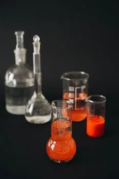
Metal-hydroxide sludge from the clarifier underflow runs at 2–4% dry solids and needs to be dewatered before it leaves the site. A plate and frame filter press for metal sludge is the workhorse, with filter areas from 1 m² for a small lab/pilot train up to 500 m² for a single 100,000 t/yr precursor plant; PLC-controlled automatic plate shifters and cloth-wash systems are now standard in 2024–2026 builds. Target cake dryness is 25–35% dry solids, which is dry enough to truck and meets the handling threshold for most off-site metal refiners. Filtrate returns to the equalization basin, and cloth-wash water is recycled back to Reactor 1 to recover residual base and any carry-over flocculant.
Recovery economics matter because the metal content of the cake is significant: a typical 30% dry-solids cake from a 2,000 mg/L mixed-metal feed carries 8–15% Ni+Co+Mn by dry weight, which is high enough to be saleable to a refiner. At 2026 metal prices the recovery credit can offset 20–40% of the NaOH chemical cost, which is the single largest OPEX line in the train. A regulatory note: under 2026 EU waste codes and the Chinese GB 34330 framework, Ni/Co/Mn hydroxide cake is increasingly classified as hazardous waste if leachable thresholds (typically Ni 5 mg/L, Co 5 mg/L, Mn 10 mg/L by TCLP) are exceeded, so the press must deliver a stable cake with pH > 9 to keep the metals passivated during transport and landfill.
Frequently Asked Questions
What pH removes manganese from wastewater? Manganese precipitates as Mn(OH)₂ between pH 10.0 and 11.0, which is roughly 1.5 pH units higher than the threshold for Ni and Co in the same solution.
Can NaOH and Ca(OH)₂ be used together in coprecipitation? Yes — many NCM plants use Ca(OH)₂ for the bulk pH push in Reactor 1 and NaOH for the tight pH 10.5 ± 0.2 polish in Reactor 2, but the Ca²⁺ carryover (often 200–600 mg/L) must be managed if a downstream RO is in the train.
How is ammonia-nitrogen removed after metal precipitation? At the 2,000–5,000 mg/L NH₃-N levels typical of precursor mother liquor, biological nitrification (nitrification/denitrification) is most common, with breakpoint chlorination or air stripping used as polishing or backup options depending on the discharge limit.
Why is DAF sometimes used instead of a clarifier for metal hydroxides? Mn(OH)₂ floc is light and colloidal, especially at pH 10.5+, and settles slowly; DAF micro-bubbles (30–60 µm) attach to the floc and float it to the surface, giving faster and more complete capture than gravity settling in those conditions.
What discharge limits apply to Ni/Co/Mn in 2026? Limits are tiered by industry category, receiving water body, and region (e.g. China GB 39728-2025, EU IED Annex VI BAT-AEL, Korea ME specific effluent standards); the specific number depends on the plant location and discharge path and should be checked against the current local standard rather than a generic value.