LED wastewater treatment design uses UV-C LEDs for tertiary disinfection after solids and organics are reduced. Typical industrial trains treat 10 to 2,000 m³/day (2,600 to 530,000 US gpd). Hybrid UV-LED plus DAF or MBR trains can cut COD by 92–97% and TSS by 95–99% (per EPA 2024 benchmarks cited for multi-barrier trains), while the UV stage targets pathogen inactivation rather than bulk COD. Compared with low-pressure mercury UV, LED reactors offer instant on/off response and zero mercury inventory in the lamp.
LED Wastewater Treatment Design for Hybrid UV-LED Systems
Hybrid UV-LED trains place a validated LED array as the final barrier after turbidity control. At design fluence near 40 mJ/cm² and chamber HRT of 5–10 seconds at 20–25 °C, industrial arrays commonly target 4-log bacterial reduction when UVT is adequate. Instant start under 100 milliseconds supports flow-paced pulsing on intermittent industrial discharge.
Why Industrial Facilities Are Switching to UV-LED Disinfection
Industrial mercury UV lamps incur hazardous waste disposal costs ranging from $500 to $1,500 per lamp annually. They also need warm-up periods that limit intermittent duty. Facility managers comparing mercury and solid-state options often focus on duty cycle and spare-parts logistics. A semiconductor plant in Taiwan documented a 45% reduction in OPEX after replacing a legacy mercury UV array with a high-intensity LED UV system (2025 field data). That change removed the 15-minute warm-up of mercury lamps. It also allowed demand-responsive cycles matched to process discharge pulses.
Regulatory pressure on mercury sources is rising, but the picture is more nuanced than a single national ban. Earlier summaries referred to an EPA 2026 phase-out roadmap for mercury disinfection equipment. As of August 2026, no such EPA equipment ban is published. EU RoHS Annex III UV-lamp exemptions remain under Pack 29 review. Mercury UV lamps therefore stay available pending a Commission decision (Opsytec, August 2026). Specialty germicidal UV lamps also remain under Minamata Convention exemptions extended at COP6 in 2025 (manufacturer summary, 2026). LED arrays still remove mercury breakage risk inside the reactor. Modular capacity can grow from 100 m³/day to 2,000 m³/day by adding modules.
Current industrial applications for industrial UV-LED systems generally fall into three categories:
- Tertiary UV Disinfection: Final-stage pathogen inactivation before discharge or reuse.
- Hybrid UV-LED + DAF/MBR: UV polishing after physical and biological barriers on high-strength process water.
- Mobile/Trailer-Mounted Systems: Rapid-deployment units for remote mining sites or emergency response where compact power budgets matter.
These trains are particularly effective in UV-LED integration in silicon wafer wastewater treatment, where ultrapure reuse loops demand tight microbial control.
UV-LED Mechanism: How LED Light Inactivates Pathogens in Wastewater
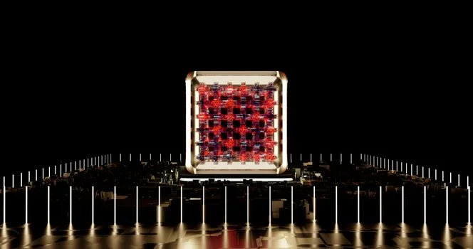
UV-LED disinfection reaches peak germicidal efficacy near 265 nm. That band sits close to the nucleic-acid absorption peak of common waterborne pathogens. Low-pressure mercury lamps emit a fixed line near 254 nm. LEDs can be tuned across roughly 260–280 nm. Research from Dalhousie University (2023) indicates that 265 nm is approximately 15–20% more effective at damaging DNA and RNA of resistant microorganisms than the mercury emission line under comparable fluence.
Inactivation proceeds in three stages. First, photon absorption occurs as UV-C penetrates the cell. Second, DNA/RNA dimerization forms improper thymine or cytosine bonds. Third, replication inhibition stops reproduction even if metabolic activity remains. Engineers size fluence in mJ/cm² against the target organism and the measured UV transmittance of the water.
| Parameter | Mercury UV (Low Pressure) | UV-LED System (2026 Spec) | Performance Impact |
|---|---|---|---|
| Peak Wavelength | 254 nm (Fixed) | 265–275 nm (Tunable) | 15% higher germicidal efficiency |
| Warm-up Time | 10–15 Minutes | Instant (<100 Milliseconds) | Enables flow-paced pulsing |
| Operating Life | 8,000–12,000 Hours | 50,000–100,000 Hours | 80% reduction in maintenance cycles |
| Energy Efficiency | ~30% Conversion | ~50–60% Conversion | Significant OPEX savings |
| Mercury Content | 5–200 mg per lamp | 0 mg | Eliminates hazardous waste risk |
Earlier tables often listed ~50–60% electrical-to-UV conversion for UV-LED systems against ~30% for mercury.Low-pressure mercury lamps at 254 nm remain near about 25% (Aqua Ultraviolet, 2026). Log reduction targets for UV-LED disinfection wastewater duty remain stringent. Current 2024 EPA-cited performance bands for a properly designed LED array include 4–6 log for E. coli, 3–5 log for norovirus, and 2–4 log for Cryptosporidium when dose and UVT are validated. Narrower LED emission (260–280 nm) avoids the non-germicidal tails of medium-pressure mercury spectra (200–300 nm).
How Do LED and Mercury Reactors Differ for Low-Energy Reuse?
LED reactors support low-energy UV disinfection for decentralized water reuse when flow is intermittent. Warm-up losses often dominate mercury duty cycles in that setting. Instant start and dimming let PLC logic match fluence to real-time flow and UVT. That pattern suits pulsed industrial reuse loops. Mercury line-source reactors still deliver high power density per fixture on continuous high-flow municipal duty. Lamp count and validated hydraulics often keep unit dose cost lower there today. For small-to-mid industrial reuse from roughly 10 to 500 m³/day at 20–25 °C, LED arrays cut idle energy and mercury handling. Large continuous plants should compare validated RED, UVT, and TCO before switching.
Hybrid LED Systems: Design Specs with DAF and MBR
Integrating UV-LED modules with Dissolved Air Flotation (DAF) or Membrane Bioreactors (MBR) allows a 20–30% reduction in required UV dosage by lowering influent turbidity and TSS. In a hybrid LED wastewater treatment architecture, UV is the polishing step in a multi-barrier train. Using a DAF system for pre-treatment in UV-LED wastewater systems produces micro-bubbles (40–60 μm) that remove 90–95% of TSS. That cut is critical because suspended solids shield pathogens from UV light through shadowing.
For high-strength industrial effluent, an Integrated MBR system for hybrid UV-LED + membrane filtration is the preferred design. The MBR’s PVDF membranes, with a 0.1 μm pore size, achieve a physical 99.9% pathogen removal. The UV-LED array then provides tertiary disinfection for residual viruses. In 2026 engineering specs, hydraulic retention times for UV-LED chambers are optimized at 5–10 seconds. That is lower than the 10–20 seconds often used for mercury systems. The difference reflects higher local power density (30–50 mW/cm²) of modern LED chips under clear UVT.
| System Component | Technical Specification (2026) | Removal Efficiency (Target) |
|---|---|---|
| DAF Pre-treatment | Rise Rate: 5–10 m/h; Bubble Size: 40 μm | 95% TSS; 60% Oil/Grease |
| MBR Module | Flux: 15–25 LMH; Pore Size: 0.1 μm | 99.9% Bacteria; 90% COD |
| UV-LED Array | Fluence: 40 mJ/cm²; Intensity: 50 mW/cm² | 99.99% Virus Inactivation |
| RO Polishing | Operating Pressure: 1.0–1.5 MPa | 99.8% Total Dissolved Solids |
What DAF Sludge Handling Supports UV-LED Disinfection?
DAF float and bottom sludge must leave the clarifier promptly so recycle turbidity stays low enough for the UV chamber. Target feed turbidity below 10 NTU before UV. Use continuous float skimming and scheduled desludging matched to oil and solids load. Poor sludge withdrawal raises TSS, drops UVT, and forces higher LED drive current to hold fluence. Pair DAF sludge thickening and dewatering capacity with the design solids mass so recycle streams do not re-seed the UV inlet.
UV-LED systems also protect downstream membranes. In RO applications, UV-C pre-treatment of feed water reduces biofouling on membranes by up to 70%. That can extend RO membrane life by 2–3 years beyond disinfection alone. The same logic applies in PCB wastewater treatment with UV-LED disinfection, where organics foul membranes quickly. A PLC-controlled chemical dosing for pH adjustment in UV-LED systems is often added to hold UVT in the design band.
LED UV vs. Mercury UV vs. Chemical Disinfection: Performance and Cost Comparison
Operational expenditure for LED-based wastewater systems averages $0.05–$0.10 per cubic meter. That band is a 30–50% reduction versus many chemical or mercury disinfection baselines under comparable duty. When evaluating wastewater treatment LED ROI, procurement teams must look past CAPEX alone. LED UV systems currently carry a 15–25% price premium over mercury systems ($80,000–$250,000 for a 100–500 m³/h capacity). Total cost of ownership often favors LED within 2 to 4 years when lamp changes and mercury disposal are counted.
Chemical disinfection with chlorine remains the lowest CAPEX option ($30,000–$100,000). It carries the highest OPEX ($0.12–$0.20/m³) and DBP risk. Chlorine reactions with organic matter form trihalomethanes regulated under EPA drinking-water rules when reuse quality is required. LED UV is a physical process that adds no chemical residual. Mercury lamps typically need replacement every 12 months at $200–$500 per lamp plus labor. LED modules are often rated for 10–15 years under industrial duty cycles.
| Metric | UV-LED System | Mercury UV System | Chlorine Dosing |
|---|---|---|---|
| CAPEX (Avg) | $120,000 | $95,000 | $45,000 |
| OPEX (per m³) | $0.07 | $0.12 | $0.18 |
| Lamp/Chemical Life | 60,000+ Hours | 10,000 Hours | Continuous Refill |
| Byproduct Risk | None | Mercury Leakage | THMs/DBPs |
| Regulatory Ease | High (CleanTech) | Medium (Hazardous) | Low (Chemical Storage) |
For a facility treating 500 m³/day, energy savings alone can exceed $12,000 annually under the original OPEX bands above. Avoided hazardous-waste fees and fewer lamp changeouts further tilt LED UV vs. mercury UV comparisons toward solid-state arrays on intermittent industrial duty. PLC-linked flow sensors can dim or pulse LEDs to the measured microbial load and UVT. Mercury lamps cannot match that response during warm-up.
Compliance Checklist: Meeting EPA, EU, and WHO Standards with LED Wastewater Systems
Earlier compliance summaries often cited a validated UV dose of at least 40 mJ/cm² for 4-log virus inactivation under EPA 40 CFR Part 141 and EU Directive 91/271/EEC. According to the EPA Ultraviolet Disinfection Guidance Manual (2006) implementing LT2ESWTR Table 1.4, the required UV dose for 4.0-log virus credit is 186 mJ/cm² (40 CFR 141.720(d)(1)). The 40 mJ/cm² value remains a common NSF Class A / European design fluence for broader pathogen control. It is not the EPA 4-log virus credit value. EHS teams should size LED arrays to the credit they claim. They should also instrument UV intensity and UVT sensors for audit trails. Unlike chemical systems that rely on residual testing, LED UV systems prove performance with continuous UVI and UVT monitoring.
Facility engineers selecting LED wastewater trains should work through this checklist:
- UV Dose Validation: Confirm third-party validation (NWRI or EPA UVDGM protocols) that the LED array delivers the required fluence at design flow and UVT.
- Redundancy Planning: Use N+1 LED module redundancy so a failed bank can be offset by raising drive current on remaining modules.
- Continuous Monitoring: Install dual UVT sensors at inlet and outlet. If transmittance drops below 70%, trigger cleaning or raise LED current.
- Documentation and Logging: Log hourly UV dose, flow, and power to SCADA for compliance reporting.
- Pre-treatment Verification: Keep upstream MBR or DAF turbidity below 10 NTU, consistent with WHO drinking-water guidance used for reuse polishing.
- Mercury Inventory Review: Document whether spare mercury lamps remain on site and how RoHS/Minamata status affects long-term spares.
- Credit vs. Design Fluence: Separate NSF/European 40 mJ/cm² design targets from EPA 186 mJ/cm² virus credit requirements before writing the permit narrative.
Following EPA UV disinfection guidelines for the credit claimed simplifies reporting. Because UV-LED treatment forms no chlorine residual, plants avoid dechlorination steps when the permit allows physical disinfection alone.
Who this is for: Plant engineers and EPC teams specifying tertiary disinfection on industrial effluent between about 10 and 2,000 m³/day. Intermittent flow, mercury handling, and reuse polishing are the usual drivers. Who should look elsewhere: Facilities that only need bulk COD/TSS removal without a disinfection credit. Continuous mega-flow municipal plants may still prefer validated mercury line-source reactors when unit dose cost is lower. Next step: Share influent UVT, turbidity, flow profile, and target log credit. A hybrid DAF/MBR plus UV-LED train can then be sized against measured water quality.
Frequently Asked Questions
What is the lifespan of UV-LED modules in wastewater treatment?
Modern UV-LED modules are commonly rated for 50,000 to 100,000 hours of operation. In a typical industrial facility running 12 hours per day, that range equates to roughly 10–15 years of service. Low-pressure mercury UV lamps remain nearer 8,000–12,000 hours, often about one year of continuous or near-continuous duty before replacement.
Can UV-LED systems handle high-turbidity wastewater?
UV-LED systems need pre-treatment when turbidity is high; keep feed turbidity below about 10 NTU with DAF or sedimentation before the chamber. Particles scatter and absorb UV-C, so pathogens in the lee of solids receive less fluence than the bulk dose calculation assumes. If UVT falls, raise intensity only after restoring solids removal, not as a permanent substitute for clarification.
Are UV-LED systems scalable for large industrial facilities?
UV-LED systems scale modularly from about 10 m³/day to over 2,000 m³/day by adding arrays. A 500 m³/h design often uses on the order of 20–30 LED modules under 2026 packaging, each controllable for flow pacing. Confirm hydraulic validation and UVT at peak flow before accepting module counts from a datasheet alone.
What UV dose should permits claim for virus credit?
EPA LT2ESWTR Table 1.4 sets 186 mJ/cm² for 4.0-log virus credit under 40 CFR 141.720(d)(1). Earlier marketing often used 40 mJ/cm² as a general design fluence aligned with NSF Class A practice, which is not the same as EPA 4-log virus credit. Match the validated RED and monitoring plan to the log credit written in the permit.
What certifications are required for LED wastewater systems?
Industrial buyers typically look for UL listing of electrical assemblies, NSF/ANSI component marks where potable or reuse contact applies, and dose validation against EPA UVDGM or NWRI protocols. Ask suppliers for full-scale validation reports at your design UVT and flow, not only chip lifetime curves. Local electrical and hazardous-area codes still govern panel and enclosure selection.