Dicing wastewater treatment for semiconductor backgrinding and wafer sawing must remove ultrafine silicon particles (<150 nm) plus soluble metals. Conventional coagulation and settling rarely capture these colloids because Brownian motion keeps them suspended. Plants using 0.01–0.1 μm ultrafiltration (UF), then reverse osmosis (RO) and ion exchange, routinely report 99%+ TSS removal and 95%+ water recovery for rinse reuse when membranes are backwashed on a 2-hour cycle.
Why Dicing Wastewater Treatment Needs Membranes First
Dicing wastewater treatment fails with clarifiers because about 80% of solids are smaller than 150 nm, below typical bacteria (0.5–5 μm). Even 300–500 mg/L polyaluminum chloride (PAC) rarely produces settleable flocs under Brownian motion. UF pores of 0.01–0.1 μm remove those fines without relying on gravity settling, which is why most fabs we size start with membranes.
Semiconductor lines also face water cost and permit pressure. A typical fab can use 1,000–3,000 m³/day on dicing and backgrinding alone. In drought-prone regions such as Taiwan and Arizona, purchased water often runs $5–$10/m³, so reclaim economics move as fast as discharge fees. Earlier industry summaries often cite TSS below 5 mg/L and copper or nickel below 0.1 mg/L as day-to-day permit targets. According to US EPA 40 CFR Part 469 Subpart A (eCFR current through 2026), the federal semiconductor ELG itself sets total toxic organics (TTO) at 1.37 mg/L (1-day maximum), fluoride at 32.0 mg/L maximum and 17.4 mg/L monthly average under BAT, and pH within 6.0–9.0; tighter TSS and metal caps usually come from state permits or POTW local limits, not from Subpart A tables.
UF Membrane Specs for Silicon Particle Removal
UF membranes rated 0.01–0.1 μm remove ultrafine silicon from dicing wastewater and deliver over 99% TSS removal when TMP stays in the design band. Polyvinylidene fluoride (PVDF) and polyethersulfone (PES) dominate the installed base. PVDF typically tolerates pH 1–13 and temperatures up to 60°C, which suits aggressive caustic cleans. PES usually trades some chemical headroom for higher flux where footprint is tight.
Flux on dicing duty commonly falls between 50 and 150 LMH (liters/m²/hour) at influent TSS of 1,000–5,000 mg/L. Most plants we size for run closer to the lower end of that flux band once silica load climbs. Keep transmembrane pressure (TMP) between 0.5 and 2.0 bar; sustained operation above 2.5 bar has been shown to cut membrane life by about 30% through irreversible fouling. Effective PVDF flat sheet membranes for ultrafiltration of dicing wastewater need a disciplined backwash: permeate backwash every 2 hours for 30 seconds, plus 0.15% NaOH chemical clean every 24 hours to hold about 95% flux recovery. Hollow-fiber modules pack densely; flat sheets trade packing density for easier single-module swap-out.
UF Membrane Performance Parameters for Dicing Wastewater
| Parameter | PVDF Membrane | PES Membrane | Notes |
|---|---|---|---|
| Pore Size | 0.01 – 0.1 μm | 0.01 – 0.1 μm | Optimized for <150 nm silicon particles |
| Typical Flux Rate (LMH) | 50 – 100 | 80 – 150 | Dependent on TSS load (1,000–5,000 mg/L) |
| Transmembrane Pressure (TMP) | 0.5 – 2.0 bar | 0.5 – 2.0 bar | Higher TMP risks irreversible fouling |
| pH Tolerance | 1 – 13 | 2 – 12 | PVDF offers broader chemical resistance |
| Temperature Tolerance | Up to 60°C | Up to 50°C | Higher temperatures reduce membrane lifespan |
| Backwash Frequency | Every 2 hours (permeate) | Every 2 hours (permeate) | 30-second duration for flux recovery |
| Chemical Cleaning | 0.15% NaOH (24 hours) | 0.15% NaOH (24 hours) | Maintains >95% flux recovery |
What Limits Semiconductor ZLD Reclaim Recovery?
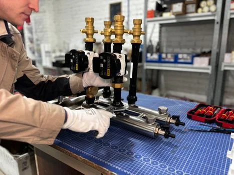
Semiconductor zero-liquid-discharge (ZLD) reclaim recovery is limited first by RO silica and salt supersaturation, then by brine handling cost, not by UF solids removal. A hybrid UF–RO–ion-exchange train protects RO from colloids, demineralizes the permeate, and polishes metals before reuse. UF strips suspended solids and ultrafine silicon so RO faces dissolved salts, metals, and residual organics rather than particle cake.
For semiconductor-grade RO systems for dicing wastewater recycling, recovery typically sits at 75–95%, with dicing streams often holding 85–90% when antiscalant and recovery setpoints match silica risk. RO permeate then goes to ion exchange. Chelating resins with iminodiacetic acid groups remove copper selectively and usually regenerate every 100–200 bed volumes with 5% HCl/NaOH. Final water often reaches TDS below 50 mg/L, TSS below 1 mg/L, and metals below 0.01 mg/L, which aligns with ASTM Type II rinse quality on many fabs.
RO reject is 10–25% of feed volume. Evaporation ponds cut CAPEX but consume land; mechanical vapor recompression (MVR) crystallizers raise CAPEX while shrinking footprint and recovering heat. PLC-controlled chemical dosing for UF membrane cleaning and RO antiscalant keeps TMP and scale under control across the train. For metal-specific polishing detail, see how to remove copper and nickel from semiconductor wastewater.
RO Recovery Rates for Dicing Waste Streams
| RO Configuration | Typical Recovery Rate (%) | Permeate TDS (mg/L) | Notes |
|---|---|---|---|
| Single-Pass RO | 75 – 85 | 50 – 150 | Cost-effective for less stringent reuse requirements |
| Double-Pass RO | 85 – 95 | <10 – 50 | Achieves higher permeate quality for critical applications |
| High-Recovery RO | 90 – 95+ | <50 | Requires advanced anti-scalant dosing and brine management |
CAPEX, OPEX, and ROI for Dicing Wastewater Recycling
A 500 m³/day dicing wastewater recycling case reported about $561,000/year in combined water-purchase and discharge savings when recovery stayed high. UF CAPEX typically runs $200–$500 per m³/day of capacity; RO runs $300–$800 per m³/day; ion exchange adds $100–$200 per m³/day; installation often adds $150–$300 per m³/day. That stacks to roughly $65,000–$180,000 for a 100 m³/day skid and $650,000–$1,800,000 for 1,000 m³/day, depending on metallurgy and brine scope.
OPEX usually breaks down as energy $0.50–$1.50 per m³, membrane replacement $0.20–$0.50 per m³, chemicals $0.10–$0.30 per m³, and labor $0.20–$0.40 per m³. Payback commonly lands at 1.5–2.5 years where water is expensive. Discharge fees of about $0.10–$0.50/m³ in the U.S. or €0.50–€2.00/m³ in the EU, plus avoided non-compliance exposure often quoted at $10,000–$50,000 per day, move the ROI as much as membrane price. For packaged layouts, see skid-mounted UF-RO systems for semiconductor fabs.
CAPEX & ROI for Dicing Wastewater Recycling Systems
| Component | Estimated CAPEX ($/m³/day capacity) | 100 m³/day System Est. CAPEX | 1,000 m³/day System Est. CAPEX |
|---|---|---|---|
| UF System | $200 – $500 | $20,000 – $50,000 | $200,000 – $500,000 |
| RO System | $300 – $800 | $30,000 – $80,000 | $300,000 – $800,000 |
| Ion Exchange | $100 – $200 | $10,000 – $20,000 | $100,000 – $200,000 |
| Installation | $150 – $300 | $15,000 – $30,000 | $150,000 – $300,000 |
| Total Estimated CAPEX | $750 – $1,800 | $75,000 – $180,000 | $750,000 – $1,800,000 |
ROI Sensitivity Analysis: Payback Period vs. Water Cost
| Water Cost (USD/m³) | Discharge Fee (USD/m³) | Estimated Annual Savings (500 m³/day system) | Estimated Payback Period (Years) |
|---|---|---|---|
| $2.00 | $0.20 | $365,000 | 2.0 – 4.0 |
| $5.00 | $0.50 | $912,500 | 1.0 – 2.0 |
| $8.00 | $0.80 | $1,460,000 | 0.7 – 1.5 |
Discharge Limits and Permitting for Semiconductor Wastewater
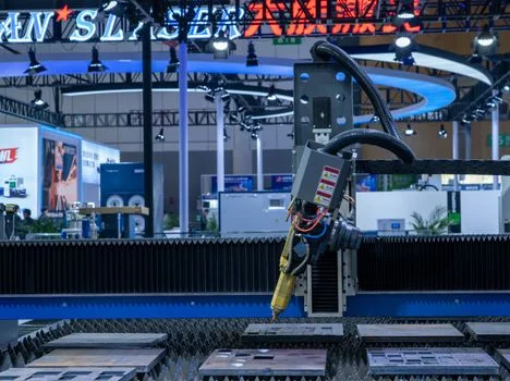
US EPA 40 CFR Part 469 remains the federal electrical and electronic components ELG baseline for semiconductor process wastewater. As verified on eCFR (current through 2026), Subpart A semiconductor limits center on TTO at 1.37 mg/L (1-day maximum), fluoride at 32.0/17.4 mg/L under BAT, and pH 6.0–9.0. Earlier guidance used TSS <5 mg/L and copper or nickel <0.1 mg/L as practical discharge targets; those figures still appear in many local permits and in the comparison table below, but they are not the federal Subpart A ELG rows. EU IED 2010/75/EU and Taiwan EPA 105-02-A001 set different monthly averages, so multi-site fabs must design to the strictest applicable permit, not a single global number.
ZLD mandates are strongest in water-stressed jurisdictions such as Singapore and Taiwan, where reclaim often must approach 100% of the targeted process stream. Hybrid UF–RO–ion-exchange trains produce reuse-grade permeate and shrink brine volume for evaporators or crystallizers. Permit upgrades commonly take 6–12 months and need engineering reports, pilot data, and impact assessments. Seasonal feed swings and underestimated silica or fluoride loads remain the usual review failures. For nitrogen-bearing rinse streams outside the dicing cut, see treating nitrogen compounds in semiconductor rinse water.
Semiconductor Wastewater Discharge Limits: U.S., EU, and Taiwan
| Parameter | U.S. EPA (40 CFR Part 469) | EU (IED 2010/75/EU) | Taiwan (EPA 105-02-A001) |
|---|---|---|---|
| Total Suspended Solids (TSS) | <5 mg/L | <35 mg/L (monthly average) | <20 mg/L |
| Copper (Cu) | <0.1 mg/L | <0.5 mg/L | <0.1 mg/L |
| Nickel (Ni) | <0.1 mg/L | <0.5 mg/L | <0.1 mg/L |
| pH | 6 – 9 | 6 – 9 | 6 – 9 |
| Chemical Oxygen Demand (COD) | N/A | <125 mg/L (monthly average) | <100 mg/L |
| Total Dissolved Solids (TDS) | N/A | N/A | <1500 mg/L (if applicable) |
What Scaling Challenges Affect ZLD Reclaim?
Silica and salt scaling, not UF solids breakthrough, usually cap semiconductor ZLD reclaim recovery once RO concentration factors rise. A flux drop exceeding 20% within 24 hours on the UF stage still signals particle or organic fouling and needs immediate diagnosis. Sharp TMP spikes after a short run often mean particle accumulation; slow TMP climb points to organic fouling or mineral scale.
Compare TMP before and after a standard backwash to quantify recoverable fouling. Laser diffraction on the feed shows whether coarse grit is bypassing prefilters. Chemical recovery tests with 0.15% NaOH for organics or 0.5% citric acid for scale identify the dominant foulant. Operators should keep the 2-hour permeate backwash on dicing duty and use a 30-minute 0.15% NaOH soak when organic recovery stalls. Installing pre-filtration systems to protect UF membranes from large particles, such as 50 μm cartridge filters, extends membrane life. Hold feed turbidity below 5 NTU and watch online TMP trends before irreversible cake forms. On RO, high-silica dicing brine often needs 2–5 mg/L phosphonate antiscalant and recovery capped near 80–85% unless brine polishing is sized for higher concentration.
Who This Is For and Next Step
This guide fits process engineers and EPC teams sizing reclaim for wafer dicing or backgrinding with TSS in the 1,000–5,000 mg/L range and a reuse or ZLD target. Plants discharging only coarse slurry that settles below permit limits without membranes should look elsewhere. Selection checklist: confirm particle size below 150 nm; set UF TMP at 0.5–2.0 bar; match RO recovery to silica risk; size ion exchange for copper polish; decide pond versus MVR brine; verify local TSS/metal limits beyond 40 CFR Part 469 Subpart A. Share your flow, silica, and permit sheet through our request-quote form for a duty-specific UF–RO mass balance.
Frequently Asked Questions
What is the best membrane material for dicing wastewater?
PVDF usually wins where chemical cleans are frequent because it tolerates about pH 1–13 and temperatures up to 60°C on dicing duty. PES is the better pick when flux and footprint dominate, often delivering 80–150 LMH versus roughly 50–100 LMH for PVDF under the same TSS band of 1,000–5,000 mg/L. Match material to cleaning chemistry first, then to hydraulic capacity.
How often should UF membranes be replaced?
PVDF membranes on well-maintained dicing trains typically last 3–5 years when TMP stays at 0.5–2.0 bar and caustic cleans hold flux recovery near 95%. PES modules more often run 2–4 years because their chemical window is narrower. Replacement intervals shorten if backwash slips past the 2-hour cycle or if prefiltration above 50 μm is skipped.
Can RO systems handle high-silica dicing wastewater?
Yes, RO can treat high-silica dicing wastewater if silica supersaturation is controlled with antiscalant and recovery limits. Dose about 2–5 mg/L of a phosphonate-based antiscalant and hold recovery near 80–85% unless a brine concentrator is designed for higher silica. UF pretreatment remains mandatory so colloids do not seed scale on the RO surface.
What is the biggest mistake on dicing reclaim trains?
Skipping adequate pre-filtration before UF is the costliest operating error on dicing lines. Coarse grit accelerates cake fouling and can cut membrane life even when pore size is correct for <150 nm silicon. A 50 μm cartridge stage before UF often extends membrane life by 30–50% and keeps the 2-hour backwash effective.
Are there alternatives to UF for dicing wastewater?
Dissolved air flotation can remove particles larger than about 1 μm and some coagulated colloids, but it does not reliably capture the <150 nm silicon fraction that dominates dicing wastewater. UF remains the practical barrier that brings TSS low enough for stable RO reclaim. Use DAF only as coarse pretreatment, not as the sole solids barrier before high-recovery RO.