Hydrofluoric Acid Wastewater Treatment System Design to Spec and Cost Targets
A hydrofluoric acid wastewater treatment system neutralizes HF with calcium hydroxide at pH 8.5–9.0, precipitates CaF₂, then clarifies and polishes with DAF, MBR or RO. Installed CAPEX spans roughly $200K–$5M by flow and train type; OPEX runs mainly on chemicals, energy and membrane replacement.
Semiconductor and PCB plants often see influent fluoride from several hundred ppm to above 1,000 ppm. Calcium hydroxide dosing at pH 8.5–9.0 commonly achieves about 95% fluoride removal as CaF₂. Hybrid DAF-RO trains can polish residual fluoride to less than 2 ppm when permits or zero-discharge goals require it. Installed CAPEX typically ranges from about $200K for basic neutralization to over $5M for high-flow MBR-RO systems, with OPEX dominated by chemicals and membrane replacement.
The stream itself is unusually aggressive. According to the Hydrofluoric Acid reference (Wikipedia), HF is a major component of Wright etch and buffered oxide etch used on silicon wafers, and it attacks glass even though hydrogen fluoride is only a weak acid in dilute aqueous solution. That combination — etch-tool origins plus relentless corrosivity — is why fabs segregate HF rinses into a dedicated train instead of mixing them into general plant sewerage.
Why HF Wastewater Systems Fail: 3 Hidden Risks in Semiconductor and PCB Plants
A 2023 EPA fine of $1.2M was levied against a Texas semiconductor plant for repeated fluoride exceedances, a clear signal of the penalties attached to inadequate hydrofluoric acid wastewater treatment (source: EPA Enforcement Database). In semiconductor and printed circuit board (PCB) plants, HF wastewater complexity often creates compliance gaps. One critical risk is premature fouling of reverse osmosis (RO) membranes, which can cut uptime by 5–10% and raise OPEX by $50K–$200K per year for a typical plant (per 2024 Hydropure Water data). Fouling usually follows weak pre-treatment that leaves calcium fluoride scale or silica on the membrane.
Simple pH adjustment alone rarely meets strict fluoride limits. Neutralization is the first step, but fluoride removal still needs controlled precipitation to CaF₂ plus polishing such as dissolved air flotation (DAF) or RO. Skipping those stages keeps effluent above permit limits and raises fine risk. A Korean PCB manufacturer avoided $800K in annual fines after upgrading to a hybrid DAF-RO train that cut fluoride from 1,200 ppm influent to less than 2 ppm.
RO Membrane Fouling Calcium Fluoride Scale: PCB Plant Checklist
RO membrane fouling by calcium fluoride scale is the single most expensive failure mode in PCB fluoride trains. The working checklist is short: keep RO feed SDI low, hold feed pH inside the membrane window of 6.0–8.0, dose antiscalant ahead of the high-pressure pumps, and schedule cleaning every 3–6 months. Track differential pressure daily so cleaning starts before irreversible scale locks in. Plants that skip the DAF or UF stage upstream are the ones buying $15K–$50K replacement elements ahead of schedule.
Chemical Neutralization for Hydrofluoric Acid Wastewater Treatment
Calcium Hydroxide Fluoride Precipitation pH Range: Why 8.5–9.0
Calcium hydroxide fluoride precipitation works best at pH 8.5–9.0, reaching about 95% fluoride removal (per EPA 2024 benchmarks). Running below pH 8.0 often drops removal to 70% or less because CaF₂ solubility rises in acidic water. Exceeding pH 9.5 increases calcium carbonate and hydroxide scaling, which burdens downstream filters. The chemistry is favorable at any pH: calcium fluoride is practically insoluble in water, with a solubility of 0.016 g/L at 20 °C (Wikipedia, Calcium Fluoride), so nearly every precipitated crystal leaves the liquid phase.
Semiconductor HF Wastewater Neutralization Design: Dosing and Kinetics
Semiconductor HF wastewater neutralization design starts from stoichiometry and then bends for real water. The stoichiometric ratio is about 1.32 kg Ca(OH)₂ per kg HF, and plant dosing usually sits at 1.2–1.5 kg Ca(OH)₂ per kg HF to cover impurities and load swings. Overdosing can raise sludge volume by 30–50% and worsen pH-related scale. Reaction time for 95% fluoride removal is generally 30–60 minutes in a well-mixed reactor.
Retention near 90 minutes or longer can grow denser CaF₂ crystals that settle and dewater more easily. Below 10°C, reaction rate can slow by about 20%, so plants may extend retention or raise dose. Heating to 25–30°C can cut chemical use by as much as 15% by speeding the reaction. Site jar tests, not textbook curves, set the final numbers.
Sodium hydroxide (NaOH) reacts faster and is easier to handle as a liquid, but it costs more and forms soluble sodium fluoride that still needs a fluoride removal stage. Precise control usually requires an automatic chemical dosing system to hold pH and reagent ratio steady.
| Parameter | Optimal Range/Value | Impact of Deviation | Notes |
|---|---|---|---|
| Neutralizing Agent | Calcium Hydroxide (Ca(OH)₂) | N/A | Most cost-effective; produces insoluble CaF₂ |
| Target pH Range | 8.5–9.0 | <8.0: Lower F- removal (<70%); >9.5: Increased scaling | Critical for CaF₂ insolubility |
| Ca(OH)₂ Dosing Rate | 1.2–1.5 kg per kg HF | Overdosing: 30–50% sludge volume increase | Stoichiometric ratio: 1.32 kg/kg HF |
| Reaction Time | 30–60 minutes | <30 min: Incomplete reaction; >90 min: Improved CaF₂ crystal growth | For 95% fluoride removal |
| Temperature | 25–30°C | <10°C: 20% slower kinetics; >30°C: 15% chemical reduction | Influences reaction speed and chemical consumption |
Fluoride Removal Technologies: DAF vs. MBR vs. RO for Zero-Discharge Compliance
Dissolved Air Flotation (DAF) systems remove about 80–90% of fluoride from pre-treated wastewater and often leave 50–100 ppm after floating CaF₂ solids. DAF works well as primary or secondary solids removal after neutralization. CAPEX for DAF units serving 10–100 m³/h typically falls between $200K–$800K. HydropureWater offers high-efficiency DAF systems for fluoride removal for industrial HF trains.
Membrane Bioreactor (MBR) systems achieve about 90–95% fluoride-related solids and organics control and commonly leave 20–50 ppm fluoride when biology plus membranes treat co-contaminants. MBRs suit HF wastewater with meaningful organic load. CAPEX usually sits between $500K–$2M. Integrated MBR systems keep footprint compact while polishing suspended solids.
Reverse Osmosis (RO) can reduce fluoride to less than 2 ppm for zero-discharge or high-purity reuse. CAPEX commonly ranges from $1M–$5M because membranes and pre-treatment dominate cost. OPEX stays high from energy use and cleaning every 3–6 months, or replacement after fouling by residual CaF₂ or silica. HydropureWater provides RO systems for zero-discharge fluoride compliance for demanding industrial feeds.
DAF RO Hybrid Fluoride Removal Zero Discharge: Sizing the Train
DAF RO hybrid trains balance a bulk fluoride cut with final polishing below 2 ppm, which is the combination most semiconductor and PCB plants end up buying. CAPEX for DAF-RO hybrids typically ranges from $1.5M–$5M. PVDF membranes generally resist HF better than polyamide in aggressive pH swings. Fouling control needs antiscalant dosing, RO-feed pH control, and scheduled chemical cleans. More complex streams often use hybrid DAF-MBR-RO systems for semiconductor wastewater and PCB wastewater treatment systems with HF handling to cover mixed contaminant loads.
| Technology | Fluoride Removal Efficiency | Typical Effluent F- (ppm) | CAPEX (10-100 m³/h) | Key Advantages | Key Disadvantages | Best Application |
|---|---|---|---|---|---|---|
| DAF (Dissolved Air Flotation) | 80–90% | 50–100 | $200K–$800K | Cost-effective pre-treatment, good for suspended solids | Limited to bulk removal, requires polishing | Pre-treatment, primary fluoride removal |
| MBR (Membrane Bioreactor) | 90–95% | 20–50 | $500K–$2M | Effective for organic-rich wastewater, good effluent quality | Higher CAPEX than DAF, membrane fouling, not for zero-discharge alone | HF wastewater with significant organic load |
| RO (Reverse Osmosis) | >99% | <2 | $1M–$5M | Achieves zero-discharge compliance, high purity effluent | High CAPEX & OPEX, sensitive to fouling, demanding pre-treatment | Zero-discharge, high-purity water reuse, final polishing |
| Hybrid (e.g., DAF-RO) | >99.5% | <2 | $1.5M–$5M | Combines benefits, optimized for high removal and compliance | Complex integration, higher overall CAPEX | Semiconductor, PCB, high-tech manufacturing |
CAPEX and OPEX Breakdown: How Much Does HF Wastewater Treatment Cost?
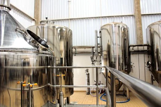
A basic chemical neutralization train for about 10 m³/h of hydrofluoric acid wastewater usually costs $200K–$400K in CAPEX. That scope covers reaction tanks, dosing pumps, mixers, and basic sludge handling. Annual OPEX typically runs $50K–$100K, led by Ca(OH)₂ consumption, labor, and mixing or pumping energy.
A DAF-RO hybrid sized near 50 m³/h commonly needs $1.5M–$3M CAPEX for the DAF, UF or MF pre-treatment, RO skid, and controls. Annual OPEX often reaches $200K–$400K from neutralization chemicals, antiscalants, membrane replacement, and high-pressure pumping. RO elements can cost $15K–$50K per 8-inch element and last about 3–5 years with disciplined cleaning.
A high-flow MBR-RO train near 100 m³/h can require $3M–$5M CAPEX and $300K–$600K annual OPEX. Costs rise with biology, membrane cleaning, energy, and sludge disposal at about $50–$150 per ton after dewatering.
HF Wastewater Treatment CAPEX OPEX: Semiconductor Multipliers
HF wastewater treatment CAPEX and OPEX for semiconductor sites carries sector multipliers that still apply in many bids: about +30% for semiconductor purity and materials rules, +20% for photovoltaic plants, and +10% for chemical plants. The adders buy higher-alloy contact parts, cleaner controls, and redundancy on the polish stage. Fabs quoting against a general-industry number should expect the low end only when reuse is off the table.
| System Type & Capacity | Typical CAPEX | Typical OPEX (Annual) | Primary OPEX Drivers | Notes |
|---|---|---|---|---|
| Basic Neutralization (10 m³/h) | $200K–$400K | $50K–$100K | Chemicals (Ca(OH)₂), Labor, Energy | Suitable for less stringent discharge limits |
| DAF-RO Hybrid (50 m³/h) | $1.5M–$3M | $200K–$400K | Chemicals, Membrane Replacement, Energy | Effective for high fluoride removal to <2 ppm |
| MBR-RO System (100 m³/h) | $3M–$5M | $300K–$600K | Chemicals, Membrane Replacement, Energy, Sludge Disposal | Best for high-flow, organic-rich wastewater, zero-discharge |
| RO Membrane Replacement | N/A | $15K–$50K per 8-inch element | Membrane fouling, age | Lifespan: 3–5 years with proper cleaning |
| Sludge Disposal | N/A | $50–$150 per ton | Dewatering, landfill fees | CaF₂ sludge typically non-hazardous |
Regulatory Compliance: EPA, China GB, and Industry-Specific Fluoride Limits
U.S. fluoride limits for industrial dischargers are set mainly in facility NPDES permits, not by a single nationwide semiconductor number. Earlier materials listed a 4 ppm fluoride limit under 40 CFR Part 415 for most industrial categories. Current eCFR text for 40 CFR Part 415 Subpart BC (sodium fluoride production) instead sets pretreatment standards for existing sources at 50 mg/L fluoride as a maximum for any 1 day for discharges to publicly owned treatment works, while BPT requires no discharge of process wastewater pollutants to navigable waters (eCFR, current). The older 4 ppm figure should be treated as background only unless a site permit states that value.
Earlier texts also cited EPA 2024 guidance recommending 2 ppm for some semiconductor plants. That 2 ppm figure was not confirmed as a standalone EPA industrial effluent guideline in this review; many fabs still see local permits or reuse goals drive effluent fluoride near or below 2 ppm. Non-compliance penalties in U.S. practice can still range from about $10K to over $1M per violation, depending on severity and duration.
In China, earlier guidance used GB 8978-1996 Integrated Wastewater Discharge Standard values of 10 ppm fluoride for new semiconductor plants and 15 ppm for general industrial discharge. National electronic-industry coverage now sits under GB 39731-2020 (Electronic Industry Water Pollutant Discharge Standard), which Anhui Provincial Ecology and Environment Bureau cites as the national framework for semiconductor wastewater management (policy interpretation, 2023). Provincial rules such as DB34/4294—2022 may tighten selected parameters further. The European Union Industrial Emissions Directive still lists a BAT-AEL near 15 ppm fluoride for parts of the chemical sector. Japan's Water Pollution Control Act is commonly cited at 8 ppm fluoride, and South Korea's Water Quality Conservation Act at 10 ppm.
Monitoring records deserve the same discipline as the process design, because unanticipated results are what inspectors read first. Quarterly review entries in plant logs are often worded exactly like this example: "review 2025 q2 wastewater 6. hf_2025.07.03_wms_edd ww report. we find an unanticipated result for “6:2 fts” (detect value is 0.02 μg/l, which has not been detected in the last three sampling events). we create a wms event report to record this unanticipated result." An unexpected surfactant hit recorded that way, with a formal event report behind it, is the audit trail that keeps a minor anomaly from becoming a permit finding.
Compliance teams should map fluoride monitoring into NPDES or local discharge permits and verify the currently binding standard before locking process design.
| Regulatory Body/Standard | Fluoride Discharge Limit | Applicable Industry/Notes |
|---|---|---|
| U.S. EPA (40 CFR Part 415) | 4 ppm | Most industrial categories |
| U.S. EPA (2024 Guidance) | 2 ppm | Some semiconductor plants, for water reuse |
| China GB 8978-1996 | 10 ppm | New semiconductor plants |
| China GB 8978-1996 | 15 ppm | General industrial discharge |
| EU Industrial Emissions Directive (IED) | 15 ppm | BAT-AEL for chemical industry |
| Japan (Water Pollution Control Act) | 8 ppm | General industrial discharge |
| South Korea (Water Quality Conservation Act) | 10 ppm | General industrial discharge |
What Limits Semiconductor ZLD Reclaim and Recovery?
Semiconductor zero liquid discharge reclaim is limited mainly by calcium fluoride scaling, silica deposition, and residual fluoride that foul RO membranes after neutralization. When pre-treatment leaves CaF₂ fines or high hardness in the RO feed, recovery often stalls as differential pressure rises and cleanings shorten. Plants that keep RO feed SDI low, hold feed pH inside membrane limits (typically 6.0–8.0), and dose antiscalant before the high-pressure stage sustain higher reclaim rates. Practical recovery ceilings still depend on TDS, fluoride, and silica at the RO inlet, not on the RO brand alone.
Downstream of the membranes, the brine stage sets the real energy budget. Reference data on ZLD note that pre-concentration steps are able to recover up to 60–80% of the water before thermal treatment, while mechanical vapor compression brine units draw about 14.86 kWh/m³ electrical (Wikipedia, Zero Liquid Discharge). For a compact HF-focused process map, compare this page with the 2026 HF wastewater engineering specs for hybrid DAF-RO.
How Do US Fabs Approach ZLD for New Campuses?
US semiconductor fabs planning new campuses usually treat ZLD as a water-sustainability and permit strategy, not as a single unit operation. Campus designs often segregate HF etch wastewater, neutralize to CaF₂, clarify with DAF or settlers, then polish with UF and RO before brine concentration. Reclaim targets typically send RO permeate to cooling makeup or lower-grade rinse loops while concentrate goes to crystallizers or off-site disposal. Early mass-balance work on fluoride load, silica, and peak flow prevents undersized reaction tanks and RO trains that cannot hold recovery during tool ramp-up.
Step-by-Step HF Wastewater Treatment Process Design
Design of a hydrofluoric acid wastewater treatment system starts with influent characterization: HF concentration, pH, average and peak flow, plus co-contaminants such as metals, solids, or organics. Semiconductor wastewater may contain 500–2,000 ppm HF with 100–300 ppm TOC, which changes polishing needs.
Next, select the neutralizing chemical. Calcium hydroxide is usually preferred because it forms insoluble CaF₂ at lower reagent cost. Sodium hydroxide reacts faster but yields soluble fluoride that still needs removal. Dose from stoichiometry near 1.32 kg Ca(OH)₂ per kg HF, then confirm with jar tests on site water.
Size the reaction tank for 30–60 minutes retention at design flow, and provide 1.5–2 times peak-flow volume where swings are large. Keep pH control automatic so the reactor stays inside 8.5–9.0. Choose DAF or settling for bulk CaF₂ solids, then add RO when the permit or reclaim goal needs effluent below about 2 ppm fluoride.
Finish with sludge handling. CaF₂ sludge is often non-hazardous but still needs dewatering. A plate and frame filter press or centrifuge can raise cake solids to about 30–40% before landfill disposal under local rules.
Who this is for: process engineers and EPC teams sizing HF neutralization, DAF, and RO for semiconductor, PCB, or specialty chemical plants. Who should look elsewhere: sites with only dilute fluoride and no HF etch load may need a simpler adsorptive polish rather than a full hybrid train. Next step: send influent fluoride, flow, and the binding discharge or reclaim limit through our HF wastewater quotation request so the CAPEX band can be narrowed before detailed design. For block-by-block depth, the companion How to Treat HF Wastewater: 2026 Engineering Specs, Hybrid DAF-RO Systems & Zero-Discharge Compliance page expands each stage.
Frequently Asked Questions
What is the most cost-effective HF wastewater treatment method?
The cheapest method depends on the fluoride limit you must meet. For looser limits above about 50 ppm, basic Ca(OH)₂ neutralization plus settling is usually cheapest, with CAPEX about $200K–$400K and OPEX about $50K–$100K per year at 10 m³/h. For limits below 2 ppm or zero-discharge goals, hybrid DAF-RO trains cost more up front ($1.5M–$3M) and to run ($200K–$400K per year), but often win on total cost by avoiding fines and enabling reuse.
How do I prevent RO membrane fouling in HF treatment?
RO fouling in HF service is prevented mainly by strong solids and scale control before the membranes. Use DAF or UF to remove residual CaF₂, dose antiscalant, keep RO feed pH inside the membrane window (typically 6.0–8.0), and clean on a 3–6 month cycle with acid and alkaline cleaners. Track feed SDI and differential pressure so cleaning starts before irreversible scale locks in.
What are the discharge limits for fluoride in the semiconductor industry?
Semiconductor fluoride limits are permit-specific and often tighter than general industrial tables. Earlier U.S. summaries cited 4 ppm under 40 CFR Part 415 and 2 ppm guidance for some fabs; current Part 415 Subpart BC categorical pretreatment for sodium fluoride production lists 50 mg/L fluoride as a maximum day value for POTW dischargers, so the site NPDES or local permit remains the binding number. China still references GB 8978-1996 values of 10 ppm for new semiconductor plants, while GB 39731-2020 now frames national electronic-industry control.
Can I reuse treated HF wastewater?
Yes, treated HF wastewater can be reused when polishing reaches the quality of the receiving process. RO or ion exchange is usually required to hold fluoride near or below 1–2 ppm and to cut metals and TDS. Common uses include cooling-tower makeup, non-contact cooling, and lower-grade rinse water. Ultra-pure loops still need further polish beyond a standard industrial RO permeate.
What are the safety risks of HF wastewater treatment?
HF wastewater treatment carries burn and systemic toxicity risks even at dilute concentrations. The Hydrofluoric Acid reference (Wikipedia) notes that poisoning can occur readily through exposure of skin or eyes, inhalation, or ingestion, and that burns may not initially be painful. Required controls include acid-resistant gloves, face protection, splash goggles and chemical suits, plus calcium gluconate gel, spill kits, showers and eyewash stations at the dosing area. Enclosed transfer and strong ventilation reduce inhalation exposure during chemical handling and tank maintenance.