Monocrystalline silicon wastewater treatment plant design must handle hydrofluoric acid up to 5% w/w, SiO2 above 1,000 mg/L, and phosphorus above 50 mg/L from saw damage removal and PSG etching. Hybrid DAF-RO-MBR plants cover this duty from $500K to $15M CAPEX.
Monocrystalline Silicon Wastewater Treatment Plant Design at a Glance
A sound design starts from the contaminant load: HF up to 5% w/w, SiO2 above 1,000 mg/L, and phosphorus above 50 mg/L from saw damage removal and PSG etching. A 2025 benchmark study (EPA Region 9) found 0.1 μm PVDF membranes with DAF at 20–40 m/h achieve 98% TSS removal and 95% HF neutralization.
The same study benchmarked those trains against EU Industrial Emissions Directive (IED) 2010/75/EU limits for fluoride (<15 mg/L) and phosphorus (<2 mg/L). Design intent follows the discharge pathway: direct discharge demands tighter polishing than sewer discharge.
Why Monocrystalline Silicon Wastewater Requires Specialized Treatment
Monocrystalline silicon solar cell manufacturing generates complex, high-strength wastewater streams that demand advanced treatment to prevent regulatory non-compliance and operational failures. The primary sources are wafer preparation and cell fabrication. Saw damage removal and texturing typically account for 60–70% of total wastewater volume, carrying HF and HNO3 concentrations up to 5% w/w and SiO2 often exceeding 1,000 mg/L (pv-tech.org, 2024).
Subsequent steps sharpen the profile. Phosphorus silicate glass (PSG) etching and emitter formation introduce significant phosphorus (P >50 mg/L), while screen printing contributes heavy metals such as nickel (Ni) and copper (Cu), demanding specific pretreatment strategies (Google Patents, CN202465417U). Untreated, these streams pose substantial environmental and operational risks: HF is corrosive and toxic and requires precise neutralization, and phosphorus plus heavy metals drive eutrophication and toxicity in receiving waters.
Silicon dioxide deserves special attention in design. Often present as colloidal silica, it is a notorious membrane foulant that severely impacts the performance and lifespan of downstream reverse osmosis (RO) systems. Fluoride is equally problematic for conventional biological treatment, because it inhibits microbial activity. Regulatory bodies — U.S. EPA 40 CFR Part 469 (Semiconductor Manufacturing) and the EU IED 2010/75/EU — impose stringent discharge limits, with typical direct-discharge values of HF <10 mg/L, SiO2 <50 mg/L, P <1 mg/L, and TSS <30 mg/L. Failure to meet them invites significant fines, operational shutdowns, and reputational damage.
| Process Step | Primary Contaminants | Typical Concentration Ranges | Associated Risks |
|---|---|---|---|
| Saw Damage Removal/Texturing | Hydrofluoric Acid (HF), Nitric Acid (HNO3), Silicon Dioxide (SiO2), Suspended Solids (TSS) | HF: 1-5% w/w, SiO2: >1,000 mg/L, TSS: >500 mg/L | Corrosion, membrane fouling, fluoride toxicity, regulatory non-compliance |
| PSG Etching/Emitter Formation | Phosphorus (P), HF, HNO3, TSS | P: >50 mg/L, HF: 0.5-2% w/w | Eutrophication, biological inhibition, regulatory non-compliance |
| Screen Printing/Metallization | Heavy Metals (Ni, Cu), Organic Solvents, TSS | Ni: 1-10 mg/L, Cu: 1-5 mg/L | Heavy metal toxicity, environmental pollution |
Hybrid DAF-RO-MBR System for Solar Cell Wastewater: Engineering Specs
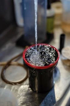
A hybrid DAF-RO-MBR system treats the complex wastewater from monocrystalline silicon production by stacking solids removal, biological treatment, and high-pressure polishing in series, meeting stringent discharge limits through optimized component engineering. The multi-stage approach manages high concentrations of HF, SiO2, and phosphorus while enabling high water recovery and minimizing fouling. Each stage carries design numbers that matter more than brand names.
The initial stage, dissolved air flotation (DAF), is crucial for removing suspended solids, colloidal silica, and precipitates formed during initial pH adjustment for fluoride. Optimal DAF systems for high-TSS monocrystalline silicon wastewater operate with a surface loading rate of 20–40 m/h and generate microbubbles typically 30–50 μm in size. Coagulant dosage — commonly polyaluminum chloride (PAC) at 50–150 mg/L — combined with a flocculant achieves 92–97% TSS removal, significantly reducing the load on subsequent membrane processes (EPA 2024 benchmarks). HydropureWater offers robust DAF systems for high-TSS monocrystalline silicon wastewater designed for this demanding application. For unit sizing fundamentals, the daf system design explainer covers surface loading rates and bubble sizing in plain terms.
Following DAF, an MBR (Membrane Bioreactor) integrates biological treatment with membrane separation, providing high-quality effluent with minimal suspended solids and enhanced removal of biodegradable organics. For monocrystalline silicon wastewater, MBR systems typically operate at MLSS concentrations of 8,000–12,000 mg/L with a Solids Retention Time (SRT) of 20–30 days. PVDF flat-sheet membranes with a 0.1 μm pore size are critical for zero-fouling performance, handling residual colloidal silica and providing a robust barrier against particulates, while integrated aeration scouring maintains flux stability (Google Patents, CN202465417U). Explore HydropureWater's advanced MBR systems with 0.1 μm PVDF membranes for zero-fouling operation. The role of an mbr for sludge separation in this train is covered in detail in our system-level guide.
The packaged equivalent of this stage is the MBR Membrane Bioreactor Wastewater Treatment System, which pairs the flat-sheet cassettes with aeration and automated cleaning on one skid. Skid-mounting shortens commissioning on crowded fab sites and keeps membrane maintenance simple. Most 50–200 m³/h plants specify it as the biological heart of the train.
The final purification step is reverse osmosis (RO) for high-purity reuse water or compliant discharge. RO systems for silicon dioxide wastewater are designed for 90–95% recovery rates at operating pressures of 8–12 bar. Membrane selection is paramount: PVDF membranes with a 0.1 μm pore size are preferred for chemical resistance and their ability to handle residual SiO2 and HF, ensuring stable performance and longevity (Facebook, 2025). HydropureWater provides reliable RO systems with PVDF membranes for silicon sludge resistance, optimized for challenging industrial applications.
Colloidal Silica Membrane Fouling Reverse Osmosis Risks
Colloidal silica is the single biggest fouling risk for the RO stage in these plants. Left untreated, it drops RO flux, raises operating pressure, and forces premature membrane replacement. The defense is sequencing: DAF with PAC dosing at 50–150 mg/L removes the bulk of colloidal silica upstream, the MBR membrane barrier catches residual particulates, and the RO then sees a feed it can polish to SiO2 removal above 99%. Plants that skip the DAF stage typically learn this lesson within one quarter of operation.
Hydrofluoric Acid Wastewater Treatment Specifications
Effective fluoride removal is a critical sub-process with its own spec sheet. After initial precipitation with calcium salts, residual fluoride is further reduced in dedicated adsorption tanks using activated alumina or bone char. Maintaining a pH of 5–6 during adsorption is crucial to achieve fluoride concentrations below 15 mg/L (Google Patents, CN202465417U). The overall flow sheet also includes equalization tanks to buffer flow and concentration spikes, automated pH adjustment for optimal chemical reactions, and a sludge dewatering stage, often utilizing filter presses for dewatering silicon sludge to <20% moisture.
| System Component | Key Engineering Specification | Performance Metric |
|---|---|---|
| Dissolved Air Flotation (DAF) | Surface Loading Rate: 20–40 m/h Microbubble Size: 30–50 μm Coagulant Dosage (PAC): 50–150 mg/L |
TSS Removal: 92–97% |
| Membrane Bioreactor (MBR) | MLSS: 8,000–12,000 mg/L SRT: 20–30 days Membrane Type: PVDF Flat-Sheet Membrane Pore Size: 0.1 μm |
BOD/COD Removal: >95% TSS in Effluent: <5 mg/L |
| Reverse Osmosis (RO) | Recovery Rate: 90–95% Operating Pressure: 8–12 bar Membrane Type: PVDF |
TDS Removal: >98% SiO2 Removal: >99% |
| Fluoride Adsorption | Adsorbent: Activated Alumina / Bone Char Operating pH: 5–6 |
Fluoride Reduction: <15 mg/L |
Fab-scale variants of this stack are covered in the Silicon Wafer Wastewater Treatment System: 2027 Engineering Specs guide, which applies the same DAF-RO-MBR logic at wafer-production scale. Buyers comparing configurations should hold that guide's CAPEX bands against the cost models below.
CAPEX and OPEX Breakdown: 2025 Cost Models for Monocrystalline Silicon Wastewater Plants
Investment in monocrystalline silicon wastewater treatment systems ranges from $500,000 to $15 million, reflecting system complexity and treatment capacity, with operational costs typically between $0.80 and $1.50 per cubic meter for advanced hybrid configurations. Benchmarked against 2024 industry surveys, these figures give plant managers and procurement teams a realistic budgeting frame for new installations or upgrades. Technology choice and target effluent quality move the number more than plant layout does.
Capital Expenditure (CAPEX) varies significantly based on the chosen treatment technology and desired effluent quality:
- Basic DAF + Chemical Dosing: For plants requiring primary treatment and moderate contaminant reduction, CAPEX typically ranges from $500,000 to $2 million. This includes equipment for chemical precipitation, flocculation, and solid-liquid separation.
- DAF-RO System: Integrating reverse osmosis for higher water purity and potential reuse, a DAF-RO system commands a CAPEX of $2.5 million to $8 million. This accounts for specialized RO membranes, high-pressure pumps, and pretreatment stages.
- Full DAF-RO-MBR with Sludge Dewatering: The most comprehensive solution, offering superior effluent quality and high water recovery, has a CAPEX between $5 million and $15 million. This includes advanced MBR modules, sophisticated controls, and dedicated filter presses for dewatering silicon sludge to <20% moisture.
Operational Expenditure (OPEX) for DAF-RO-MBR systems typically falls within $0.80–$1.50/m³ of treated wastewater. The breakdown includes:
- Energy: $0.30–$0.50/m³, primarily for pumps (DAF, RO), aeration (MBR), and mixing.
- Chemicals: $0.20–$0.40/m³, covering coagulants, flocculants, pH adjusters, membrane cleaning chemicals, and fluoride adsorbents. Automated chemical dosing systems, such as HydropureWater's automated chemical dosing for pH adjustment and coagulant addition, can optimize usage and reduce waste.
- Membrane Replacement: $0.10–$0.20/m³, a significant cost over the system's lifespan, emphasizing the importance of robust membrane selection and effective pretreatment.
- Labor & Maintenance: Remaining costs cover skilled operators, routine maintenance, and spare parts.
Key Return on Investment (ROI) drivers for advanced monocrystalline silicon wastewater treatment include:
- Water Reuse: Achieving 50–70% water recovery significantly reduces fresh water intake costs, especially in regions with high water tariffs.
- Sludge Disposal Cost Savings: Efficient dewatering reduces sludge volume, leading to savings of $50–$150/ton in disposal fees.
- Avoidance of Compliance Penalties: Non-compliance can result in fines ranging from $25,000 to $500,000 per violation, making robust treatment a critical risk mitigation strategy.
Cost-saving strategies, such as integrating solar-powered RO pumps and implementing automated chemical dosing, further enhance financial viability. For comprehensive cost analysis, consider HydropureWater's insights on 2027 hybrid DAF-RO-MBR specs for solar cell wastewater treatment plants.
| System Type | Typical CAPEX (2025 USD) | Typical OPEX Range (per m³) | Primary Benefits |
|---|---|---|---|
| DAF + Chemical Dosing | $500K – $2M | $0.50 – $0.80 | Primary TSS & HF reduction, basic compliance |
| DAF-RO System | $2.5M – $8M | $0.70 – $1.20 | High water purity, significant water reuse potential |
| Full DAF-RO-MBR with Sludge Dewatering | $5M – $15M | $0.80 – $1.50 | Superior effluent quality, maximum water reuse, full compliance |
Compliance Checklist: Meeting EPA and EU Standards for Monocrystalline Silicon Wastewater
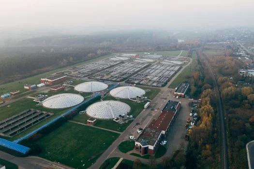
Adherence to EPA 40 CFR Part 469 and EU IED 2010/75/EU is mandatory for monocrystalline silicon wastewater discharge, with specific limits for fluoride, silicon dioxide, and phosphorus driving treatment design. Process engineers must audit their systems against these benchmarks regularly. Continuous compliance, not pass-the-inspection compliance, is what avoids costly penalties.
The U.S. EPA 40 CFR Part 469, for the Semiconductor Manufacturing Point Source Category, sets strict effluent limitations for key contaminants. For direct discharge these typically include HF <10 mg/L, SiO2 <50 mg/L, P <1 mg/L, and TSS <30 mg/L, with pH 6–9 (2025 EPA guidelines). Permits may tighten any of these values for sensitive receiving waters.
Similarly, the EU's Industrial Emissions Directive (IED) 2010/75/EU mandates Best Available Techniques (BAT) to achieve stringent effluent quality. Site limits often include fluoride <15 mg/L, phosphorus <2 mg/L, and heavy metals such as nickel (Ni <0.5 mg/L) and copper (Cu <0.5 mg/L). These values are frequently site-specific and can be tighter under local rules.
Fluoride Removal Semiconductor Manufacturing Wastewater Limits
Fluoride limits anchor the whole treatment train in semiconductor manufacturing wastewater. Calcium precipitation alone cannot reach the <10 mg/L EPA direct-discharge value reliably, which is why the activated alumina or bone char adsorption stage at pH 5–6 exists in the design. Weekly fluoride testing, continuous pH monitoring, and automated calcium-salt dosing keep the plant inside its permit band. Where reuse is the goal, RO polishing pushes fluoride far below any discharge limit.
Effective compliance requires a robust sampling and monitoring program. Continuous pH and TSS monitoring are standard practice, providing real-time performance data. Weekly testing for HF, SiO2, and P tracks specific contaminant removal efficiencies. Annual heavy metal testing ensures less frequent discharges or accumulated contaminants stay within permissible limits (pv-tech.org, 2024).
Common compliance pitfalls in monocrystalline silicon wastewater treatment include:
- pH Swings: Inconsistent pH control during HF neutralization can lead to incomplete precipitation, re-dissolution of fluoride compounds, or excursions outside regulatory pH limits.
- SiO2 Fouling: Inadequate pretreatment of colloidal silica can cause rapid fouling of RO membranes, leading to decreased flux, increased operating pressure, and premature membrane replacement, ultimately impacting effluent quality.
- Phosphorus Excursions: Variations in raw wastewater phosphorus concentrations or inefficient biological/chemical removal can result in effluent exceeding P limits, especially for sensitive receiving waters.
Addressing these challenges through optimized design and operation, like those detailed in 2027 engineering specs for silicon wafer wastewater treatment equipment, is crucial for sustained compliance.
| Parameter | EPA 40 CFR Part 469 (Direct Discharge) | EU IED 2010/75/EU (Typical BAT) | Monitoring Frequency |
|---|---|---|---|
| Hydrofluoric Acid (HF) / Fluoride | <10 mg/L | <15 mg/L | Weekly |
| Silicon Dioxide (SiO2) | <50 mg/L | <50 mg/L (as total Si) | Weekly |
| Phosphorus (P) | <1 mg/L | <2 mg/L | Weekly |
| Total Suspended Solids (TSS) | <30 mg/L | <30 mg/L | Continuous |
| pH | 6–9 | 6–9 | Continuous |
| Nickel (Ni) | (Site-specific) | <0.5 mg/L | Annually |
| Copper (Cu) | (Site-specific) | <0.5 mg/L | Annually |
Case Study: Upgrading a 50 m³/h Monocrystalline Silicon Wastewater Plant in Malaysia
A 50 m³/h monocrystalline silicon wastewater plant in Malaysia achieved full compliance by upgrading to a hybrid DAF-RO-MBR system, reducing HF from 45 mg/L to below 5 mg/L. The facility faced potential shutdown under Malaysia's Environmental Quality (Industrial Effluent) Regulations 2009, specifically limits for HF (<10 mg/L) and SiO2 (<50 mg/L). The original system — a basic DAF with chemical dosing — could not handle fluctuating loads from the wafer lines, and average effluent ran HF at 45 mg/L, SiO2 at 800 mg/L, and TSS at 200 mg/L.
HydropureWater engineered a hybrid DAF-RO-MBR system for the site. The solution used an advanced DAF unit with optimized coagulant dosing for colloidal silica and TSS removal, followed by an MBR with 0.1 μm PVDF membranes for biological treatment, and a final RO stage with specialized PVDF membranes polishing water for internal reuse. Dedicated activated alumina fluoride adsorption tanks were integrated post-DAF, operating at a controlled pH of 5–6.
The results, based on 2024 plant data, were transformative. HF fell from an average of 45 mg/L to below 5 mg/L, well within limits. SiO2 dropped from 800 mg/L to less than 20 mg/L, removing the RO fouling risk. TSS fell from 200 mg/L to below 10 mg/L, stabilizing the downstream membrane processes.
Total CAPEX for the project was $3.2 million, with OPEX settling at approximately $1.10/m³ treated. The plant reached an ROI of 3.5 years, driven by water reuse above 65% of treated effluent and the complete avoidance of compliance penalties. Key lessons: adequately sized equalization tanks to buffer influent spikes, and automated pH control to prevent membrane fouling throughout the train. Similar outcomes are detailed in 2027 engineering specs for photovoltaic wastewater treatment plants with energy autonomy.
Who this is for: process engineers and procurement leads at mono-wafer, solar cell, and semiconductor plants specifying a new treatment line or an upgrade. Who should look elsewhere: municipal sewage teams and plants with only neutral rinse water. Next step: send your effluent analysis and permit limits through our request a quote page for a sized hybrid DAF-RO-MBR proposal.
Frequently Asked Questions
What are the primary contaminants in monocrystalline silicon wastewater?
The primary contaminants include hydrofluoric acid (HF), silicon dioxide (SiO2), phosphorus (P), nitric acid (HNO3), and heavy metals (Ni, Cu) from processes like saw damage removal, PSG etching, and screen printing. HF reaches 5% w/w in texturing baths, SiO2 often exceeds 1,000 mg/L, and phosphorus tops 50 mg/L in PSG rinses. Each contaminant dictates a specific treatment stage.
Why is a hybrid DAF-RO-MBR system recommended for monocrystalline silicon wastewater?
A hybrid DAF-RO-MBR system is recommended because it combines DAF for high TSS and SiO2 removal, MBR for biological treatment and robust solids separation, and RO for polishing and high-purity water recovery. The multi-barrier approach handles complex contaminants, prevents fouling, and meets stringent discharge limits. Single-technology plants typically fail on either fluoride or silica compliance.
What are the typical RO recovery rates for silicon dioxide wastewater?
RO systems for monocrystalline silicon wastewater are typically designed for 90–95% recovery rates. Specialized PVDF membranes and effective pretreatment minimize fouling from residual silicon dioxide, and operation at 8–12 bar keeps energy in check. Pushing recovery above that band usually forces frequent CIP cycles unless silica is removed upstream.
How does HydropureWater ensure compliance with EPA 40 CFR Part 469?
HydropureWater designs to the specific 40 CFR Part 469 limits — HF below 10 mg/L, SiO2 below 50 mg/L, and P below 1 mg/L — through optimized engineering specs, continuous monitoring integration, and proven unit operations such as fluoride adsorption and advanced membrane filtration. Weekly HF, SiO2, and P testing plus continuous pH and TSS monitoring close the compliance loop.
What is the expected CAPEX for a DAF-RO-MBR system treating monocrystalline silicon wastewater?
For a full DAF-RO-MBR system including sludge dewatering, CAPEX typically ranges from $5 million to $15 million, depending on plant capacity, contaminant loads, and reuse targets. Basic DAF with chemical dosing starts near $500,000, and DAF-RO configurations fall between $2.5 million and $8 million. OPEX runs $0.80–$1.50/m³ for hybrid trains.