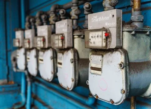
Hydrofluoric Acid Wastewater Treatment by Reverse Osmosis: 2026 Engineering Specs, 99% Recovery & Zero-Risk ZLD Blueprint
Hydrofluoric acid (HF) wastewater treatment by reverse osmosis (RO) achieves 99%+ fluoride removal and up to 90% water recovery when paired with coagulation/precipitation pretreatment. Spiral wound RO systems, equipped with polyamide membranes, deliver stable flux rates (15–25 LMH) at pH 9.5–10.5, while vibratory shear-enhanced filtration (VSEP) can further concentrate RO reject streams for zero liquid discharge (ZLD). This two-stage approach reduces thermal evaporation costs by 40–60% and meets semiconductor industry discharge limits (fluoride < 15 mg/L).
Why Hydrofluoric Acid Wastewater is a Treatment Challenge
Hydrofluoric acid (HF) is a weak acid with a pKa of 3.17, meaning it remains largely undissociated as a neutral molecule in acidic environments, which significantly complicates membrane-based separation. Unlike sulfuric or hydrochloric acid, HF is highly corrosive to silicate-based materials and toxic to biological treatment systems. In semiconductor and photovoltaic manufacturing, HF wastewater often contains fluoride concentrations ranging from 500 to 5,000 mg/L, often accompanied by hexafluorosilicic acid (H₂SiF₆) and aluminum fluoride (AlF₃) complexes. These soluble complexes resist conventional precipitation and can pass through standard filtration media if not properly destabilized.
The primary challenge for industrial engineers is that conventional lime precipitation alone typically reaches a thermodynamic limit of 8–15 mg/L of residual fluoride. While this may meet some basic discharge permits, it fails to address the stringent requirements for water reuse or the <1 mg/L limits required for ultrapure water (UPW) feedstocks. conventional methods fail to remove dissolved organics and total dissolved solids (TDS), which leads to rapid scaling in downstream equipment. According to a 2012 study published in the Journal of Hazardous Materials, the presence of co-contaminants like isopropyl alcohol (IPA) and phosphoric acid in semiconductor wastewater further inhibits fluoride settling, making a high-rejection membrane process like reverse osmosis essential for achieving compliance and resource recovery.
For facility managers, the volatility of fluoride discharge limits—often as low as 2 mg/L in sensitive watersheds—means that relying solely on chemical precipitation is a high-risk strategy. Reverse osmosis provides a physical barrier that ensures consistent effluent quality regardless of upstream chemical fluctuations, provided the feed water is properly conditioned to prevent membrane degradation.
How Reverse Osmosis Removes Fluoride from HF Wastewater

Reverse osmosis membranes, specifically polyamide thin-film composites (TFC), reject fluoride ions through a combination of size exclusion and electrostatic repulsion (the Donnan effect). Because the hydrated radius of a fluoride ion is approximately 0.35 nm, it is effectively blocked by the dense polymer matrix of an RO membrane, which typically features pore sizes in the 0.0001–0.001 μm range. However, the efficiency of this rejection is heavily dependent on the speciation of fluoride, which is controlled by the pH of the feed water.
At a pH below 3.17, fluoride exists primarily as HF (a neutral molecule), which can diffuse through the membrane polymer, resulting in rejection rates as low as 40–50%. As the pH is increased to 9.5–10.5, the fluoride dissociates into F⁻ ions, and the membrane surface becomes more negatively charged. This creates a strong electrostatic repulsion that pushes the fluoride ions away from the membrane surface, increasing rejection to 98% or higher. Spiral wound RO modules are the industry standard for this application due to their high surface area-to-volume ratio and ability to maintain stable flux rates (15–25 LMH) under high osmotic pressure. Research indicates that polyamide membranes show the highest flux stability when treating neutralized HF streams compared to cellulose acetate alternatives, which are prone to hydrolysis at the required alkaline pH levels.
| Parameter | Feed Water (Post-Pretreatment) | RO Permeate (Treated) | Rejection Rate (%) |
|---|---|---|---|
| Fluoride Concentration | 20–50 mg/L | <0.5–1.5 mg/L | 97% – 99.5% |
| pH Level | 9.5 – 10.5 | 8.5 – 9.5 | N/A |
| Total Dissolved Solids (TDS) | 1,500 – 3,000 mg/L | <50 mg/L | 98.5% – 99.8% |
| Silica (SiO₂) | <20 mg/L | <0.2 mg/L | 99% |
Pretreatment Requirements for RO in HF Wastewater Treatment
Successful RO operation in HF applications is impossible without rigorous pretreatment to reduce the fluoride load and remove scaling precursors like calcium and silica. The first stage typically involves chemical coagulation and precipitation using calcium hydroxide (Ca(OH)₂) or calcium chloride (CaCl₂). To achieve maximum fluoride reduction, engineers should maintain a 1.5–2.0x stoichiometric ratio of calcium to fluoride. This process reduces the bulk fluoride concentration from thousands of mg/L to approximately 20–50 mg/L, which protects the RO membranes from excessive osmotic pressure and rapid scaling. For high-precision control, PLC-controlled chemical dosing for HF wastewater pretreatment is recommended to manage real-time fluctuations in acid concentration.
Following precipitation, the wastewater must undergo clarification and ultrafiltration (UF). UF membranes with a pore size of 0.02–0.1 μm are critical for removing colloidal silica and suspended calcium fluoride (CaF₂) particles that can bypass traditional sand filters. A Silt Density Index (SDI₁₅) of <3 is the target for RO feed water to ensure membrane longevity. Without UF, the spiral wound RO modules would suffer from irreversible "bridging" fouling, where small particles lodge in the feed spacers. If the wastewater contains high levels of heavy metals or complexing agents, two-stage calcium fluoride precipitation as an alternative to RO may be used as a primary step before the RO polishing stage.
Finally, pH adjustment is the most critical operational variable. Before entering the RO skid, the water must be stabilized at a pH of 9.5–10.5 using sodium hydroxide (NaOH). This alkaline environment ensures that any remaining fluoride is in the ionic (F⁻) form and helps keep any residual silica in a soluble state, preventing it from precipitating as hard scale on the membrane surface. This high pH also acts as a biocide, reducing the risk of biofouling in the RO stages.
RO System Design Parameters for HF Wastewater
Engineering an RO system for HF wastewater requires a conservative design approach to account for the high scaling potential of calcium fluoride and silica. The selection of the membrane is the first priority; high-rejection polyamide thin-film composite (TFC) membranes, such as the Dow Filmtec BW30 or Hydranautics ESPA series, are preferred for their durability in high-pH cleaning cycles. The system flux should be limited to 15–25 Liters per Square Meter per Hour (LMH) at a 25°C baseline. Operating at higher flux rates increases the concentration polarization at the membrane surface, which accelerates the precipitation of fluoride salts and reduces the effective life of the elements.
Recovery rates for a standard RO system treating HF wastewater typically range from 75% to 90%. To achieve 90% recovery, a multi-stage array (e.g., a 2:1 or 3:2 configuration) is employed, where the concentrate from the first stage becomes the feed for the second stage. This maximizes water savings but requires careful monitoring of the Langelier Saturation Index (LSI) to prevent scaling in the final stage. For facilities targeting high-purity reuse, Zhongsheng Environmental industrial RO systems for HF wastewater treatment utilize variable frequency drives (VFDs) on high-pressure pumps to maintain constant flux even as water temperatures or TDS levels fluctuate.
| Engineering Spec | Standard Value | Notes/Requirements |
|---|---|---|
| Membrane Type | Polyamide TFC (Spiral Wound) | High rejection, pH tolerance 2–12 |
| Design Flux | 15 – 25 LMH | Temperature corrected to 25°C |
| System Recovery | 75% – 90% | Dependent on feed TDS and scaling inhibitors |
| Feed SDI₁₅ | < 3.0 | Requires UF or high-efficiency media filtration |
| Cleaning Frequency | Every 3 – 6 months | NaOH (pH 12) for organics; Citric Acid (pH 2) for scale |
| Operating Pressure | 150 – 400 psi | Varies based on TDS and recovery target |
Maintenance protocols must include automated Clean-In-Place (CIP) sequences. When flux declines by 10–15% or differential pressure increases by 15%, a two-step cleaning is performed: an alkaline wash (pH 11–12) to remove organic fouling and a low-pH wash (pH 2–3) using citric acid to dissolve calcium fluoride and carbonate scales. Implementing these parameters ensures a membrane lifespan of 3–5 years even in harsh industrial environments.
Treating RO Concentrate: Spiral Wound vs. VSEP for ZLD
The concentrate (reject) stream from an RO system treating HF wastewater typically contains 500–1,500 mg/L of fluoride and high levels of TDS, making it unsuitable for direct discharge. For facilities aiming for Zero Liquid Discharge (ZLD), this stream must be further concentrated to minimize the volume of water sent to expensive thermal evaporators or crystallizers. Engineers generally choose between secondary spiral wound RO and Vibratory Shear-Enhanced Processing (VSEP).
Spiral wound RO is the lower CAPEX option but is limited by the "solubility ceiling." As the concentrate becomes more saturated, calcium fluoride begins to precipitate, causing rapid fouling. Even with high-performance antiscalants, spiral RO can rarely exceed 80% recovery on concentrate streams. In contrast, VSEP technology uses high-frequency vibration to create intense shear waves at the membrane surface. This shear prevents the formation of a stagnant boundary layer (concentration polarization), allowing the system to operate at much higher solids concentrations without fouling. VSEP can achieve 90–95% recovery on RO concentrate, effectively reducing the final waste volume by up to 80% compared to secondary RO. While VSEP has a higher initial cost, the reduction in thermal evaporation energy consumption (which can cost $10–$30 per m³ of water) results in a much lower total cost of ownership for ZLD projects.
| Feature | Spiral Wound RO (Secondary) | VSEP (Vibratory Shear) |
|---|---|---|
| Recovery on Concentrate | 70% – 80% | 90% – 95% |
| Fouling Resistance | Low (Requires high pretreatment) | Very High (Handles precipitates) |
| Pretreatment Needs | Strict (SDI < 3) | Minimal (Handles high TSS) |
| ZLD Cost Impact | High (Large evaporation volume) | Low (Small evaporation volume) |
| Typical Application | Standard discharge compliance | Zero Liquid Discharge (ZLD) |
Cost Breakdown: RO + Pretreatment for HF Wastewater Treatment
Budgeting for an HF wastewater RO system requires a distinction between the capital expenditure (CAPEX) of the hardware and the ongoing operational expenditure (OPEX) driven by chemicals and energy. For a 50 m³/h (approx. 220 GPM) treatment system, the CAPEX typically ranges from $300,000 to $500,000. This includes the reaction tanks for calcium precipitation, the ultrafiltration skid, the RO skid with high-pressure pumps, and the PLC-based control system. High-grade materials like 316L stainless steel or specialized plastics (PVDF/PP) are required for pipework to resist HF corrosion, which contributes to the higher CAPEX compared to standard municipal RO systems.
The OPEX for these systems is estimated at $0.80–$1.50 per cubic meter of treated water. The largest cost driver is chemical consumption (NaOH and calcium salts), which accounts for roughly 30–40% of the OPEX. Energy consumption is relatively low (0.15–0.30/m³) due to the use of energy recovery devices and high-efficiency pumps. Membrane replacement typically accounts for $0.10–$0.20/m³, assuming a 3-year replacement cycle. For semiconductor facilities, the Return on Investment (ROI) is often realized within 2 to 4 years, primarily through the reduction in fresh water procurement costs and the avoidance of high-cost hazardous waste disposal fees.
| Cost Category | Estimated Cost (50 m³/h System) | % of Total OPEX |
|---|---|---|
| CAPEX (Equipment & Install) | $300,000 – $500,000 | N/A |
| Chemicals (NaOH, Lime, Antiscalant) | $0.20 – $0.40 / m³ | 35% |
| Energy Consumption | $0.15 – $0.30 / m³ | 25% |
| Membrane Replacement (Annualized) | $0.10 – $0.20 / m³ | 15% |
| Labor & Maintenance | $0.15 – $0.25 / m³ | 25% |
Compliance Standards for Fluoride in Industrial Wastewater
Regulatory compliance is the primary driver for adopting RO in HF wastewater management. In the United States, the EPA sets the National Effluent Limitations Guidelines (40 CFR Part 415), which generally limit fluoride discharge to <15 mg/L for many industrial categories. However, local "Point of Discharge" limits in regions like California or the Pacific Northwest can be significantly lower, often matching the Safe Drinking Water Act (SDWA) secondary standard of 2.0 mg/L to prevent dental fluorosis and skeletal issues in downstream populations.
In the European Union, Directive 2010/75/EU on industrial emissions requires the use of Best Available Techniques (BAT). For the chemical and electronics sectors, this often implies a fluoride limit of <15 mg/L for direct discharge into water bodies and <1.5 mg/L for areas where water reuse is practiced. For the semiconductor industry specifically, the SEMI F63-0701 standard provides the benchmark for ultrapure water, requiring fluoride levels to be below 1 μg/L (ppb) for certain process steps. While RO alone cannot reach 1 ppb, it is the essential "bulk removal" step that allows ion exchange polishing to reach those ultra-trace levels economically. Engineers should also consult RO treatment for general fluoride wastewater (non-HF) standards if their facility processes multiple fluoride sources.
Frequently Asked Questions
What is the maximum fluoride concentration an RO system can handle?
While RO can technically handle high concentrations, it is economically and operationally best to use chemical precipitation to reduce fluoride to <50 mg/L before RO. This prevents excessive osmotic pressure and reduces the risk of immediate membrane scaling, ensuring a stable recovery rate of 75–90%.
Why does fluoride rejection drop at low pH?
Fluoride rejection is pH-dependent because HF has a pKa of 3.17. Below pH 3, fluoride exists as a neutral HF molecule which passes easily through RO membranes. At pH 9.5–10.5, it exists as the F⁻ ion, which is rejected by the membrane's negative surface charge at rates exceeding 99%.
Can RO membranes be damaged by hydrofluoric acid?
Standard polyamide RO membranes are resistant to dilute HF, but the structural components of the RO skid (pumps, housings, and sensors) must be made of HF-resistant materials like PVDF or high-grade stainless steel. Pre-neutralizing the wastewater to pH 7–10 is the standard practice to protect the entire system.
How does RO compare to Ion Exchange for HF treatment?
RO is superior for high-volume, high-concentration streams because it removes TDS, silica, and organics simultaneously. Ion exchange (IX) is better suited as a "polishing" step after RO to reduce fluoride from 1 mg/L to parts-per-billion (ppb) levels, as IX resins saturate too quickly if used for bulk removal.
What is the typical lifespan of RO membranes in HF service?
With proper pretreatment (calcium precipitation and UF) and a pH of 9.5–10.5, polyamide membranes typically last 3 to 5 years. Frequent scaling due to poor pretreatment or improper CIP (Clean-In-Place) protocols can reduce this lifespan to less than 12 months.