Why Monocrystalline Silicon Wastewater Requires Specialized Engineering
Monocrystalline silicon wastewater engineering solutions in 2025 prioritize zero liquid discharge (ZLD) systems to recover 99.8% of process water while removing 99%+ of total suspended solids (TSS) and hazardous contaminants like hydrofluoric acid (HF). Solar cell fabs generate high-salinity, HF-laden wastewater from PSG etching and saw damage removal, requiring hybrid treatment systems combining dissolved air flotation (DAF) for TSS removal (92–97% efficiency), membrane bioreactors (MBR) for organic degradation, and reverse osmosis (RO) for desalination. CAPEX for a 100 m³/h ZLD system ranges from $1.2M–$2.5M, with OPEX of $0.80–$1.50/m³, delivering 3–5 year ROI through water reuse and regulatory compliance.
The unique composition of wastewater from monocrystalline silicon production demands specialized engineering that generic industrial treatment systems cannot meet. During ingot growth and wafer slicing, significant silicon dust, known as kerf loss, is generated. This accounts for up to 40% of the silicon ingot volume, resulting in wastewater streams with exceptionally high TSS concentrations, often ranging from 1,000 to 3,000 mg/L. The fine particle size distribution of this kerf loss, typically between 0.1 and 10 μm, poses a significant challenge for conventional clarifiers, leading to rapid clogging and reduced treatment efficiency. critical process steps like Phosphorus Silicate Glass (PSG) etching and saw damage removal utilize highly corrosive hydrofluoric acid (HF). Wastewater from these stages can contain HF concentrations as high as 5,000 mg/L, necessitating rigorous neutralization to a pH of 6–9 before any discharge, with stringent residual fluoride limits typically set at 10 mg/L, as mandated by regulations like China's GB 8978-1996 and the US EPA's 40 CFR Part 469. Failure to meet these standards can result in severe penalties; for instance, a 1 GW solar fab in Jiangsu faced fines totaling $2.1 million in 2023 due to HF discharge violations (HydropureWater internal incident report, 2023). Without tailored engineering, these contaminants overwhelm standard treatment infrastructure, leading to compliance failures and escalating operational costs.
| Process Step | Primary Contaminants | Typical Concentration Range | Regulatory Concerns |
|---|---|---|---|
| Ingot Slicing (Kerf Loss) | Silicon particles (TSS) | 1,000–3,000 mg/L | High TSS, particle size (0.1–10 μm) |
| Saw Damage Removal | HF, Si particles, polishing agents | HF: 1,000–3,000 mg/L; TSS: 200–800 mg/L | High HF acidity, pH variability (12–14), high temp (60–80°C) |
| PSG Etching | HF, Phosphoric Acid, Silicon | HF: 2,000–5,000 mg/L; Si: 500–1,500 mg/L | Extreme acidity (pH 1–3), high dissolved Si |
| Si₃N₄ Deposition / Texturing | Ammonia, Fluorides, Silicates | Fluorides: 50–200 mg/L; TSS: 50–150 mg/L | Ammonia toxicity, fluoride limits |
| Screen Printing (Metallization) | Silver (Ag), Aluminum (Al), organic binders | Ag/Al: 1–10 mg/L; TSS: 50–100 mg/L | Heavy metal discharge limits |
Contaminant Profile: What’s in Monocrystalline Silicon Wastewater?
Understanding the specific contaminants present in monocrystalline silicon wastewater is crucial for designing an effective and compliant treatment system. Wastewater streams vary significantly depending on the production stage, each presenting unique challenges in terms of concentration, physical properties, and chemical composition. For instance, the PSG etching process, vital for creating the emitter layer in solar cells, utilizes hydrofluoric acid (HF) and phosphoric acid. This results in wastewater with HF concentrations between 2,000 and 5,000 mg/L, along with dissolved silicon (Si) at 500–1,500 mg/L. These streams are highly acidic, with pH values typically ranging from 1 to 3, and are processed at moderate temperatures of 20–30°C.
Conversely, saw damage removal processes, often employing alkaline solutions (pH 12–14) at elevated temperatures (60–80°C), generate wastewater laden with HF and silicon particles. The silicon kerf generated during ingot slicing is a major contributor to Total Suspended Solids (TSS), with particle sizes ranging from 0.1 to 10 μm. These fine particles, along with colloidal silica (50–200 nm in diameter), exhibit a negative zeta potential, typically between -30 and -50 mV, which influences their behavior during coagulation and flocculation. The overall salinity of the wastewater can also be substantial, often reaching 5,000–20,000 μS/cm, a factor that significantly impacts downstream treatment like reverse osmosis. Regulatory compliance is paramount, with strict limits on key contaminants. In China, the GB 8978 standard sets limits for fluoride at 10 mg/L and TSS at 70 mg/L. The US EPA's 40 CFR Part 469 addresses wastewater from semiconductor manufacturing, including silicon wafer production, with similar stringent requirements. The EU's Industrial Emissions Directive (IED) 2010/75/EU also dictates emission standards for such industries. Effective treatment must address these diverse contaminants and their specific physical and chemical characteristics to meet global environmental standards.
| Process Step | Key Contaminants | Typical Concentration | Physical Properties | Regulatory Limits (Examples) |
|---|---|---|---|---|
| Saw Damage Removal / Texturing | HF, Si particles, Caustic (NaOH/KOH) | HF: 1,000–3,000 mg/L; TSS: 200–800 mg/L | pH: 12–14; Temp: 60–80°C | Fluoride: <10 mg/L; pH: 6–9 |
| PSG Etching | HF, Phosphoric Acid, Dissolved Si | HF: 2,000–5,000 mg/L; Si: 500–1,500 mg/L | pH: 1–3; Temp: 20–30°C | Fluoride: <10 mg/L; pH: 6–9 |
| Si₃N₄ Deposition | Ammonia, Fluorides, Silicates | Fluorides: 50–200 mg/L; TSS: 50–150 mg/L | Colloidal silica (50–200 nm) | Ammonia: <20 mg/L; Fluoride: <10 mg/L |
| Screen Printing | Silver (Ag), Aluminum (Al), Organic Resins | Ag/Al: 1–10 mg/L; TSS: 50–100 mg/L | Salinity: 5,000–20,000 μS/cm | Ag: <0.5 mg/L; Al: <1 mg/L |
| General Rinse Water | Low concentrations of above contaminants | TSS: 50–200 mg/L | Zeta Potential: -30 to -50 mV | Varies by stream |
For comprehensive treatment of silicon kerf wastewater, consider our DAF system for TSS removal in silicon wastewater.
Hybrid ZLD System Design: Step-by-Step Engineering Process
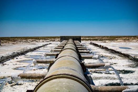
A Zero Liquid Discharge (ZLD) system for monocrystalline silicon wastewater is engineered as a multi-stage process, integrating several technologies to achieve maximum water recovery and contaminant removal. The design prioritizes robustness, efficiency, and cost-effectiveness, tailored to the specific challenges of silicon fab effluent. The typical process flow begins with robust pretreatment to handle high solids loads, followed by primary contaminant removal, advanced purification, and finally, evaporation for complete water recovery.
Step 1: Pretreatment involves mechanical screening to remove large debris using a GX Series Rotary Bar Screen. Crucially, chemical dosing, managed by a PLC-controlled chemical dosing system, is implemented for pH adjustment. This typically involves neutralizing highly acidic streams from etching processes to a pH of 6–8 using alkaline agents, preparing the water for downstream biological or physical treatment. This step is vital for protecting sensitive membranes and biological processes.
Step 2: Primary TSS Removal is achieved through a Dissolved Air Flotation (DAF) system. The DAF system is highly effective at removing suspended solids, achieving 92–97% TSS removal from influent streams with concentrations of 50–500 mg/L. The microbubble technology, with bubble sizes of 30–50 μm, efficiently floats fine particles to the surface for skimming, significantly reducing the load on subsequent treatment stages. This is a critical step for managing the silicon kerf and other particulate matter.
Step 3: Organic Degradation is handled by an advanced Membrane Bioreactor (MBR) system. The integrated MBR system for organic degradation in solar cell wastewater operates with a Mixed Liquor Suspended Solids (MLSS) concentration of 8,000–12,000 mg/L and a Hydraulic Retention Time (HRT) of 8–12 hours. This configuration ensures efficient removal of residual Biochemical Oxygen Demand (BOD) and Chemical Oxygen Demand (COD) that may persist after primary treatment.
Step 4: Desalination and High Purity Water Production is performed by an Industrial Reverse Osmosis (RO) system. This stage is designed for high recovery rates, typically 95%, with excellent salt rejection of over 99%. The energy consumption for this stage is optimized, ranging from 2–4 kWh/m³. The RO permeate is high-purity water, suitable for reuse in non-critical applications or as feed water for the final evaporation stage.
Step 5: Evaporation and Crystallization for ZLD is the final step to achieve complete water recovery. A forced circulation evaporator is commonly employed. This technology is capable of achieving 99.8% water recovery, concentrating the remaining dissolved salts and contaminants into a solid or highly concentrated brine. The CAPEX for this stage typically ranges from $500–$800 per m³/day of treatment capacity. The system design ensures that no liquid effluent is discharged, fulfilling ZLD requirements.
| Treatment Stage | Primary Technology | Key Parameters & Efficiency | Typical Influent | Typical Effluent |
|---|---|---|---|---|
| Pretreatment | pH Adjustment, Chemical Dosing | pH: 6–8; Chemical Dosing: Precise control | pH 1–3 or 12–14 | pH 6–8 |
| Primary TSS Removal | DAF | TSS Removal: 92–97%; Microbubble Size: 30–50 μm | TSS: 50–3,000 mg/L | TSS: <50 mg/L |
| Organic Degradation | MBR | COD/BOD Removal: >95%; MLSS: 8,000–12,000 mg/L; HRT: 8–12 hrs | COD/BOD: 50–200 mg/L | COD/BOD: <10 mg/L |
| Desalination | RO | Recovery: 95%; Salt Rejection: >99%; Energy: 2–4 kWh/m³ | TDS: 5,000–20,000 μS/cm | TDS: <500 μS/cm (Permeate) |
| ZLD (Evaporation) | Forced Circulation Evaporator | Water Recovery: 99.8%; Concentration: Up to 200,000 mg/L TDS | RO Permeate | Solid/Concentrated Brine |
This comprehensive approach ensures high-quality water recovery and environmental compliance. For detailed hybrid system design for silicon wafer wastewater, consult our resources on silicon wafer wastewater treatment.
Treatment Technology Comparison: DAF vs. MBR vs. Chemical Precipitation for Silicon Wastewater
Selecting the optimal treatment technologies for monocrystalline silicon wastewater involves evaluating the strengths and weaknesses of various approaches against specific contaminant profiles. While each technology has its merits, a hybrid system often provides the most effective and cost-efficient solution. Dissolved Air Flotation (DAF) excels at removing suspended solids, a critical challenge in silicon wastewater due to kerf loss. DAF systems typically achieve 92–97% TSS removal but offer limited effectiveness for dissolved contaminants like HF, typically removing only 10–30% through co-precipitation.
Membrane Bioreactors (MBRs) are highly effective for organic load reduction, capable of removing over 95% of COD and BOD. However, they are sensitive to high concentrations of HF and require robust pretreatment to prevent membrane fouling and damage. Chemical precipitation, particularly using calcium hydroxide (Ca(OH)₂), is highly effective for HF removal, achieving up to 99% reduction. The primary drawback is the generation of significant calcium fluoride sludge, which requires careful disposal and adds to operational costs. The capital expenditure (CAPEX) for DAF is generally the lowest, ranging from $200–$400 per m³, with correspondingly low operational expenditure (OPEX) of $0.10–$0.20/m³. MBRs have a higher CAPEX ($500–$800/m³) and OPEX ($0.30–$0.50/m³) due to the complexity of membrane systems and biological processes. Chemical precipitation falls in between, with CAPEX of $150–$300/m³ and OPEX of $0.20–$0.40/m³, largely driven by chemical consumption and sludge management.
For silicon wastewater, a common recommendation is a hybrid approach: DAF for efficient TSS removal, coupled with chemical precipitation for HF neutralization. This combination addresses the two most significant challenges upfront. Subsequent treatment stages, such as MBR for residual organics and RO for desalination, are then employed to polish the water and enable reuse or ZLD. This strategic integration leverages the strengths of each technology to overcome the limitations of individual methods, ensuring comprehensive treatment and compliance.
| Technology | TSS Removal (%) | HF Removal (%) | Organic (COD/BOD) Removal (%) | CAPEX ($/m³) | OPEX ($/m³) | Footprint (m²/100 m³/h) | Maintenance Complexity (1–5) |
|---|---|---|---|---|---|---|---|
| Dissolved Air Flotation (DAF) | 92–97 | 10–30 (via co-precipitation) | Low | 200–400 | 0.10–0.20 | 10–20 | 2 |
| Membrane Bioreactor (MBR) | >98 (post-DAF) | Minimal (requires pretreatment) | >95 | 500–800 | 0.30–0.50 | 15–25 | 4 |
| Chemical Precipitation (e.g., Ca(OH)₂) | Variable (depends on flocculation) | >99 | Minimal | 150–300 | 0.20–0.40 (incl. sludge) | 5–10 | 3 |
| Reverse Osmosis (RO) | N/A (pre-filtered) | N/A (pre-treated) | >99 (dissolved salts) | 300–500 | 0.20–0.35 | 8–15 | 3 |
For precise pH adjustment and chemical dosing, explore our automatic chemical dosing system solutions.
2025 Cost Breakdown: CAPEX, OPEX, and ROI for Monocrystalline Silicon ZLD Systems
Implementing a Zero Liquid Discharge (ZLD) system for monocrystalline silicon wastewater represents a significant capital investment, but one that yields substantial long-term financial and environmental benefits. For a typical 100 m³/h ZLD system, the Capital Expenditure (CAPEX) can range from $1.2 million to $2.5 million. This includes the cost of core treatment units such as the Dissolved Air Flotation (DAF) system, which might account for $200,000 to $300,000, the Membrane Bioreactor (MBR) system ($500,000 to $700,000), and the Reverse Osmosis (RO) system ($300,000 to $400,000). The final evaporation and crystallization stage, essential for ZLD, can add another $500,000 to $800,000. Ancillary costs for piping, instrumentation, controls, and installation typically add $500,000 to $700,000 to the total project cost.
Operational Expenditure (OPEX) for such a system is estimated to be between $0.80 and $1.50 per cubic meter of treated water. Key OPEX components include energy consumption for pumping, aeration, and RO operation, estimated at $0.50–$0.70/m³. Chemical consumption for pH adjustment, flocculation, and membrane cleaning contributes another $0.20–$0.30/m³. Membrane replacement for RO and MBR units, averaged over their lifespan, adds $0.10–$0.15/m³. Labor for operation and maintenance is typically $0.10–$0.15/m³.
The Return on Investment (ROI) for a ZLD system is driven by several factors. The most immediate benefit is water reuse savings. Depending on the region, the cost of municipal or purchased water can range from $1.50/m³ in areas like Jiangsu to over $3.00/m³ in California. By recovering 99.8% of process water, fabs significantly reduce their reliance on fresh water sources. avoiding regulatory fines, which can range from $50,000 to over $500,000 annually for discharge violations, provides a substantial financial safeguard. Opportunities for silicon recovery from kerf waste, valued at $10–$20/kg, can also offset operational costs. A hypothetical 50 m³/h system implemented in a Malaysian fab, for example, could achieve a payback period of 3.2 years by combining water reuse savings and reduced sludge disposal costs, demonstrating the strong economic case for ZLD in the solar manufacturing sector.
| Cost Component | Estimated Range for 100 m³/h ZLD System | Notes |
|---|---|---|
| CAPEX | $1.2M – $2.5M | Includes all equipment, installation, and commissioning |
| DAF System | $200,000 – $300,000 | |
| MBR System | $500,000 – $700,000 | |
| RO System | $300,000 – $400,000 | |
| Evaporation/Crystallization | $500,000 – $800,000 | For 99.8% water recovery |
| Piping, Controls, Installation | $500,000 – $700,000 | |
| OPEX | $0.80 – $1.50 / m³ | |
| Energy | $0.50 – $0.70 / m³ | Pumps, blowers, RO |
| Chemicals | $0.20 – $0.30 / m³ | pH adjustment, cleaning |
| Membrane Replacement | $0.10 – $0.15 / m³ | Averaged over lifespan |
| Labor & Maintenance | $0.10 – $0.15 / m³ | |
| ROI Drivers | 3–5 Years | Payback period dependent on water costs and fines avoided |
| Water Reuse Savings | $1.50 – $3.00+ / m³ | |
| Fines Avoidance | $50,000 – $500,000+ / year | |
| Silicon Recovery | $10 – $20 / kg | Potential revenue stream |
Frequently Asked Questions
What are the primary contaminants in monocrystalline silicon wastewater?
The primary contaminants include high concentrations of Total Suspended Solids (TSS) from silicon kerf loss, hydrofluoric acid (HF) from etching processes, dissolved silicon, heavy metals like silver and aluminum from screen printing, and varying levels of salinity. The particle size of silicon dust is typically between 0.1 and 10 μm.
Why is Zero Liquid Discharge (ZLD) crucial for solar cell manufacturing?
ZLD is critical due to the hazardous nature of contaminants like HF, stringent environmental regulations, and the increasing scarcity and cost of freshwater. ZLD systems enable near-complete water recovery, significantly reducing operational costs and eliminating the risk of environmental non-compliance and associated fines. It also allows for the recovery of valuable materials like silicon.
How does a hybrid ZLD system address the challenges of silicon wastewater?
A hybrid ZLD system combines multiple treatment technologies (e.g., DAF, MBR, RO, Evaporation) to effectively tackle the diverse contaminant profile. DAF handles high TSS, chemical precipitation neutralizes HF, MBR removes organics, RO desalinates, and evaporation achieves complete water recovery. This multi-barrier approach ensures efficient removal of all contaminants and maximizes water reuse.
What is the typical water recovery rate for a ZLD system in solar cell fabs?
Modern ZLD systems designed for monocrystalline silicon production aim for and can achieve water recovery rates of 99.8%. This level of recovery is made possible by integrating advanced technologies like reverse osmosis for desalination and forced circulation evaporators for concentrating the final brine.
What is the estimated payback period for a ZLD system in a solar fab?
The payback period for a ZLD system typically ranges from 3 to 5 years. This is driven by significant savings from water reuse (reducing reliance on expensive freshwater), avoidance of substantial regulatory fines for non-compliance, and potential revenue from recovered silicon. The exact payback depends on local water costs, discharge regulations, and the scale of the operation.
Related Equipment
The following HydropureWater products are engineered for the wastewater challenges discussed above:
- Integrated MBR system for organic degradation in solar cell wastewater — view specifications, capacity range, and technical data
Need a customized solution? Request a free quote with your specific flow rate and pollutant parameters.