Integrated Circuit Nickel Wastewater Treatment: 2025 Hybrid System Design with 99.9% Removal & Cost Breakdown
Integrated circuit (IC) fabs generate nickel wastewater with concentrations up to 50–500 mg/L, exceeding China GB 21900-2008 limits (1.0 mg/L) and US EPA standards (0.25 mg/L for freshwater). Hybrid treatment systems combining chemical precipitation (pH 9.5–10.5, 90–95% removal), ultrafiltration (0.01 μm pore size), and ion exchange (99.9% final polishing) achieve 99.9%+ nickel removal while recovering 85–95% of water for reuse. CAPEX ranges from $1.2M–$4.5M for 50–200 m³/h systems, with OPEX of $0.80–$2.50/m³ treated (HydropureWater data, 2025).Why Nickel Wastewater is a Critical Challenge for IC Fabs
IC fabrication processes typically generate nickel wastewater with concentrations ranging from 50–500 mg/L, significantly surpassing global discharge limits (HydropureWater field data, 2024). Nickel in IC wastewater primarily originates from electroless nickel plating (EN), a critical process for creating corrosion-resistant and conductive layers on wafers, as well as from certain etching and chemical-mechanical planarization (CMP) slurries. These concentrated nickel streams pose substantial environmental and regulatory compliance risks for semiconductor fabs worldwide. For instance, China's GB 21900-2008 standard sets a stringent limit of 1.0 mg/L for total nickel in direct discharge, while US EPA standards for freshwater discharge are even lower at 0.25 mg/L. The consequences of non-compliance are severe, including fines up to $50,000 per day in the United States under EPA regulations and potential production halts in China for violations of GB 21900-2008. Beyond immediate penalties, persistent discharge violations can damage a fab's reputation, impact investor confidence, and hinder future expansion permits. Economically, the semiconductor industry's reliance on vast quantities of chemicals means that approximately 85% of chemical reagents used in IC fabrication ultimately enter the wastewater stream (Nature, 2026). Within this complex effluent, nickel often constitutes 15–25% of the total heavy metal load, making its effective removal a high-priority and high-cost challenge. The urgency for robust, high-efficiency integrated circuit nickel wastewater treatment systems is paramount for fabs aiming for sustainable operations and continuous production.Hybrid Nickel Wastewater Treatment: Process Design and Engineering Specs
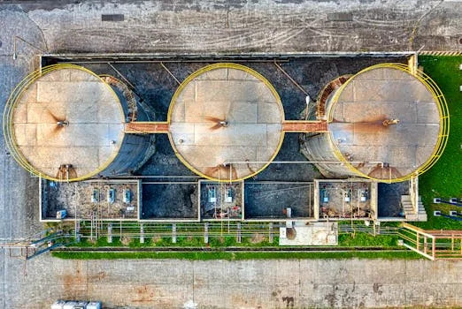
The typical hybrid system for nickel removal in IC fabs includes:
- Stage 1: Chemical Precipitation. This initial stage targets bulk nickel removal. Wastewater pH is adjusted to 9.5–10.5 using alkaline reagents like sodium hydroxide (NaOH) or calcium hydroxide (Ca(OH)₂). At this pH range, nickel ions (Ni²⁺) precipitate as insoluble nickel hydroxide (Ni(OH)₂). Optimal mixing speeds of 200–300 rpm ensure efficient reagent dispersion and floc formation, followed by a retention time of 30–60 minutes for complete reaction. This stage typically achieves 90–95% nickel removal, reducing concentrations from 50–500 mg/L down to 5–50 mg/L. Effective PLC-controlled chemical dosing for nickel precipitation is crucial for maintaining optimal pH and minimizing chemical consumption.
- Stage 2: Ultrafiltration (UF). Following chemical precipitation, ultrafiltration serves to remove residual suspended solids, colloidal nickel, and any unprecipitated nickel hydroxide particles that might escape conventional clarification. UF systems utilize polyvinylidene fluoride (PVDF) membranes with pore sizes typically around 0.01 μm. Operating with flux rates of 50–100 LMH (liters per square meter per hour), UF achieves 95–98% recovery of the treated water, further reducing nickel concentrations to below 1 mg/L, and preparing the water for subsequent advanced treatment.
- Stage 3: Ion Exchange (IX). For final polishing and to meet stringent discharge limits, ion exchange is employed. Chelating ion exchange resins, such as Purolite S930, are highly effective in selectively binding residual nickel ions. These resins can polish effluent to concentrations below 0.1 mg/L nickel. Typical resin capacity ranges from 1.2–1.8 equivalents per liter (eq/L), with regeneration required every 10–15 bed volumes, depending on influent nickel load. Regeneration is typically performed using an acid (e.g., H₂SO₄) followed by a caustic (e.g., NaOH).
- Optional Stage 4: Reverse Osmosis (RO) for ZLD. For facilities aiming for zero-liquid-discharge (ZLD) or requiring ultrapure water for reuse, reverse osmosis (RO) systems are integrated. RO membranes, such as the BW30-400 series, can achieve up to 95% water recovery from the ion exchange effluent, producing permeate with nickel concentrations often below 0.01 mg/L. Operating pressures typically range from 15–25 bar. The concentrated reject stream from the RO systems for nickel polishing and water recovery can then be directed to evaporators or crystallizers for further volume reduction and solids recovery.
The table below summarizes the key engineering specifications for each stage:
| Treatment Stage | Primary Function | Key Parameters/Specs | Nickel Removal Efficiency | Typical Effluent Ni (mg/L) |
|---|---|---|---|---|
| Chemical Precipitation | Bulk Ni removal | pH 9.5–10.5 (NaOH/Ca(OH)₂), Mixing 200–300 rpm, Retention 30–60 min | 90–95% | 5–50 |
| Ultrafiltration (UF) | Suspended solids, colloidal Ni removal | 0.01 μm PVDF membranes, Flux 50–100 LMH, 95–98% water recovery | >90% (of remaining Ni) | 0.5–5 |
| Ion Exchange (IX) | Final polishing | Chelating resin (e.g., Purolite S930), Capacity 1.2–1.8 eq/L, Regeneration 10–15 BV | >95% (of remaining Ni) | <0.1 |
| Reverse Osmosis (RO) (Optional for ZLD) | High purity water recovery, ZLD pre-treatment | BW30-400 membranes, 15–25 bar operating pressure, 95% water recovery | >99% (of remaining Ni) | <0.01 |
Compliance Matrix: China GB vs. US EPA vs. EU Nickel Discharge Limits
Meeting diverse global discharge standards for nickel requires a clear understanding of regional regulations and the corresponding treatment system capabilities. Semiconductor fabs operating internationally must navigate a complex landscape of environmental compliance, where limits can vary significantly based on the receiving water body and local environmental sensitivity.The primary nickel discharge limits relevant to IC fabs are:
- China GB 21900-2008 (Discharge Standard of Water Pollutants for Electroplating Industry): This standard sets a limit of 1.0 mg/L for total nickel in direct discharge. For facilities discharging into sensitive areas, a much stricter limit of 0.1 mg/L applies. Meeting the 1.0 mg/L standard can typically be achieved with a combination of chemical precipitation and ultrafiltration. However, for the 0.1 mg/L sensitive area limit, the addition of ion exchange or even reverse osmosis is usually necessary.
- US EPA (Environmental Protection Agency) Standards: The US EPA sets various limits depending on the receiving water body and intended use. For freshwater discharge, the limit is 0.25 mg/L. For saltwater discharge, it is 0.52 mg/L. If the discharge impacts drinking water sources, the limit can be as low as 0.1 mg/L. To consistently meet the 0.25 mg/L freshwater standard, a hybrid system incorporating chemical precipitation, ultrafiltration, and ion exchange is often required. The 0.1 mg/L limit for drinking water sources frequently necessitates the inclusion of reverse osmosis.
- EU Industrial Emissions Directive (IED) (Best Available Techniques Reference Document for the Production of Non-Ferrous Metals): The EU IED specifies Best Available Techniques Associated Emission Levels (BAT-AELs). For surface water discharge, the BAT-AEL for nickel is typically 0.5 mg/L. This level is generally achievable with a robust chemical precipitation and ultrafiltration system, potentially augmented by a basic ion exchange stage for added security.
A detailed comparison of global discharge standards for semiconductor wastewater, including nickel, is crucial for system design.
| Regulatory Body/Standard | Nickel Discharge Limit (Total Ni) | Recommended Hybrid Treatment System | Compliance Notes |
|---|---|---|---|
| China GB 21900-2008 | 1.0 mg/L (Direct Discharge) | Chemical Precipitation + Ultrafiltration | Requires consistent operation, pH control. |
| China GB 21900-2008 | 0.1 mg/L (Sensitive Areas) | CP + UF + Ion Exchange (or RO) | Demands advanced polishing for stringent limits. |
| US EPA (Freshwater) | 0.25 mg/L | CP + UF + Ion Exchange | Ion exchange critical for achieving sub-mg/L levels. |
| US EPA (Drinking Water Sources) | 0.1 mg/L | CP + UF + Ion Exchange + RO | RO systems often necessary for highest purity. |
| EU IED (BAT-AEL) | 0.5 mg/L (Surface Water) | CP + UF (+ optional basic IX) | Achievable with robust primary and secondary treatment. |
2025 Cost Breakdown: CAPEX, OPEX, and ROI for Nickel Wastewater Systems
Capital Expenditure (CAPEX):
For a typical 50 m³/h nickel wastewater treatment system incorporating chemical precipitation, ultrafiltration, and ion exchange, the CAPEX generally ranges from $1.2M–$1.8M. This estimate includes design, equipment procurement (tanks, pumps, filters, resin vessels, automation), installation, and commissioning. When a facility opts for a Zero-Liquid-Discharge (ZLD) system, which adds reverse osmosis and further concentration technologies like evaporators or crystallizers, the CAPEX increases significantly, typically ranging from $2.5M–$4.5M for similar capacities (HydropureWater cost modeling, 2025). Larger systems, such as those for 200 m³/h, will scale these costs upwards.Operational Expenditure (OPEX):
OPEX for nickel wastewater treatment systems varies based on the complexity and automation level. For non-ZLD systems (CP + UF + IX), OPEX typically falls within $0.80–$1.50/m³ of treated water. This includes costs for chemical reagents (NaOH, coagulants, flocculants, acids for regeneration), energy consumption (pumps, mixers), labor, routine maintenance, resin replacement (every 3–5 years), and membrane cleaning/replacement. For ZLD systems, the OPEX increases to $1.80–$2.50/m³ due to higher energy demands for RO and evaporators, increased chemical use for anti-scalants, and more intensive maintenance. A detailed cost analysis for nickel treatment systems provides a comprehensive breakdown.Return on Investment (ROI) Drivers:
Investing in advanced nickel wastewater treatment offers several compelling ROI drivers for IC fabs:- Water Recovery: Hybrid systems can recover 85–95% of treated water, significantly reducing reliance on fresh water intake and associated costs, especially in water-stressed regions. This can translate to millions of dollars in savings annually for large fabs.
- Nickel Sludge Resale: The nickel-rich sludge generated from precipitation can be a valuable byproduct. If processed to achieve >99% purity, this nickel can be sold to metal smelters for $500–$1,200 per ton, offsetting treatment costs and contributing to a circular economy.
- Avoided Fines and Production Halts: Compliance avoids hefty regulatory fines (e.g., $50,000/day in the US) and safeguards against costly production shutdowns due to environmental violations. These avoided costs represent a significant financial return.
Case Study: A 200 m³/h integrated circuit nickel wastewater treatment system implemented at a major fab in Taiwan achieved a 3-year payback period. This rapid ROI was primarily driven by substantial water reuse, which reduced fresh water consumption by 90%, coupled with revenue generated from high-purity nickel recovery, illustrating the economic viability of these advanced systems.
| System Type | Capacity (m³/h) | Estimated CAPEX (2025) | Estimated OPEX (per m³ treated) | Key ROI Drivers |
|---|---|---|---|---|
| CP + UF + IX | 50 | $1.2M–$1.8M | $0.80–$1.50 | Avoided Fines, Partial Water Recovery (85%), Sludge Recycling |
| CP + UF + IX + RO (ZLD) | 50 | $2.5M–$4.5M | $1.80–$2.50 | Max Water Recovery (95%+), Max Sludge Recycling, Full Compliance |
| CP + UF + IX + RO (ZLD) | 200 | $6.0M–$12.0M | $1.50–$2.20 | Significant Water Savings, High-Volume Sludge Revenue, Enhanced Reputation |
How to Select the Right Nickel Treatment System for Your Fab
Choosing the optimal integrated circuit nickel wastewater treatment system requires a systematic decision framework that aligns technical capabilities with specific operational and regulatory requirements. A mismatch can lead to compliance issues, inflated costs, or insufficient treatment performance.Follow these steps to ensure a well-informed selection:
- Step 1: Characterize Wastewater Thoroughly. Begin by conducting a detailed analysis of your fab's nickel wastewater. This includes precise influent nickel concentrations (e.g., 50–500 mg/L), average and peak flow rates (m³/h), and the presence of co-contaminants such as fluoride, copper, or TMAH (tetramethylammonium hydroxide). The presence of other heavy metals or complexing agents can significantly impact the effectiveness of chemical precipitation and ion exchange resins, necessitating pre-treatment or specialized resin selection. Understanding the wastewater matrix is foundational for effective system design.
- Step 2: Define Discharge Requirements Clearly. Identify the specific local, regional, and national discharge standards that your fab must meet. Determine whether your goal is direct discharge to a public water body, discharge to a municipal sewer system, or achieving zero-liquid-discharge (ZLD) for maximum water reuse. For instance, if the target is <0.1 mg/L nickel for sensitive receiving waters (e.g., China GB 21900-2008 sensitive area limit), then ion exchange or RO will be essential beyond basic precipitation and ultrafiltration.
- Step 3: Evaluate Footprint Constraints. Industrial wastewater treatment systems can occupy significant space. Assess your fab's available footprint for the treatment facility. Consider whether a skid-mounted, modular system is feasible for rapid deployment and flexibility, or if a custom-built, larger-scale solution is required. Space limitations often drive decisions towards more compact, high-density technologies like membrane filtration over conventional settling tanks.
- Step 4: Compare CAPEX/OPEX Trade-offs. Analyze the balance between capital expenditure (CAPEX) and operational expenditure (OPEX) for different system configurations. While a basic chemical precipitation + UF system has lower CAPEX, it might incur higher OPEX if non-compliance fines are frequent or if water reuse is foregone. Adding ion exchange, for example, might increase CAPEX by 15-20% and OPEX by approximately $0.30/m³ due to resin and regeneration costs, but it can reduce nickel to <0.1 mg/L, unlocking significant water reuse potential and ensuring compliance with the strictest limits.
- Step 5: Assess Automation Needs. Determine the level of automation required for your fab's operations. A fully automated system, featuring PLC-controlled chemical dosing for nickel precipitation, automated filter backwashing, and remote monitoring, reduces labor costs and improves process stability. Conversely, a more manually operated system might have lower initial CAPEX but could lead to higher labor costs and less consistent performance. Consider the trade-off between initial investment in automation and long-term operational efficiency and reliability.
Frequently Asked Questions

What is the most cost-effective nickel removal technology for IC wastewater?
For 90–95% nickel removal, chemical precipitation combined with ultrafiltration (CP + UF) is the most cost-effective initial technology. For polishing to achieve <0.1 mg/L, ion exchange is the most cost-effective advanced treatment stage.Can nickel sludge from IC wastewater be recycled?
Yes, nickel sludge from IC wastewater can be recycled if its purity exceeds 99%. This high-purity nickel can be sold to metal smelters, typically fetching $500–$1,200 per ton, offsetting treatment costs and promoting circular economy principles.What are the maintenance requirements for ion exchange resins?
Ion exchange resins require regular regeneration, typically every 10–15 bed volumes, depending on the influent nickel concentration and flow rate. The resin media itself usually needs to be replaced every 3–5 years due to fouling or degradation.How does nickel wastewater treatment integrate with ZLD systems?
In Zero-Liquid-Discharge (ZLD) systems, the permeate from the reverse osmosis (RO) stage, following nickel treatment, can be extensively reused within the fab. The concentrated reject stream from the RO is then sent to evaporators or crystallizers for further volume reduction and solids recovery, minimizing liquid discharge.What are the energy consumption ranges for nickel treatment systems?
Energy consumption for nickel treatment systems ranges from 0.5–1.2 kWh/m³ for basic chemical precipitation + ultrafiltration systems. For full Zero-Liquid-Discharge (ZLD) systems, which include RO and evaporators, energy consumption can increase to 2.0–3.5 kWh/m³ due to the higher pressure requirements of RO and the thermal energy for evaporation.Related Equipment
- PLC-controlled chemical dosing for nickel precipitation — view specifications, capacity range, and technical data
- RO systems for nickel polishing and water recovery — view specifications, capacity range, and technical data
- MBR systems for combined organic and nickel removal — view specifications, capacity range, and technical data
Need a customized solution? Request a free quote with your specific flow rate and pollutant parameters.