SiC (silicon carbide) wastewater treatment solutions achieve 99%+ TSS removal and 92–97% COD reduction for industrial effluents, leveraging SiC membranes’ chemical inertness and high flux rates (50–200 LMH). Unlike polymeric membranes, SiC systems resist fouling from abrasive particles (e.g., SiC grinding sludge) and operate at pH 0–14, making them ideal for semiconductor, photovoltaic, and high-tech manufacturing. Hybrid designs combining SiC MBRs with DAF and chemical dosing can meet zero-liquid-discharge (ZLD) standards, with CAPEX ranging from $1.2M–$3.5M for 50–500 m³/h systems (2025 data).
Why SiC Membranes Outperform Polymeric and Ceramic Alternatives for Industrial Wastewater
Silicon carbide membranes possess a Mohs hardness of 9.5, effectively eliminating the risk of surface abrasion from high-solids industrial effluents such as semiconductor grinding sludge or metal oxide particulates. Many semiconductor plant managers transition to SiC due to the failure of polymeric PVDF membranes, which often suffer from irreversible fouling and mechanical degradation when exposed to sharp, abrasive "fines" generated during wafer dicing and backgrinding processes. While polymeric membranes typically require replacement every 3 to 5 years in these aggressive environments, SiC membranes maintain structural integrity for 10+ years, significantly lowering the total cost of ownership.
Sic membranes are chemically inert, allowing for continuous operation across the entire pH spectrum (0–14). This is a critical advantage in industrial wastewater treatment engineering, as it enables the direct treatment of acidic etch baths or highly alkaline cleaning streams without extensive pH neutralization pretreatment. In contrast, PVDF membranes are restricted to a pH range of 2–11, and traditional Al₂O₃ ceramic membranes often show signs of degradation outside pH 1–12. The naturally hydrophilic surface of SiC, combined with a high porosity of 40–50%, facilitates membrane flux rates of 50–200 LMH. This high-throughput capability allows engineers to reduce the physical footprint of the treatment facility by 30–50% compared to polymeric MBR installations.
Thermal resistance is another engineering benchmark where SiC excels. These membranes can tolerate temperatures up to 800°C, supporting high-temperature steam sterilization (SIP) processes that are often required in pharmaceutical or food-grade wastewater applications. A 2024 case study of a semiconductor fab in Taiwan demonstrated that switching from PVDF to SiC modules reduced annual membrane replacement costs by 70%. The facility previously struggled with membrane punctures caused by SiC grinding particles; the implementation of a real-world SiC wastewater treatment project eliminated this failure mode entirely.
| Property | SiC Membrane | Polymeric (PVDF) | Ceramic (Al₂O₃) |
|---|---|---|---|
| Mohs Hardness | 9.5 | 3–4 | 9.0 |
| pH Range | 0–14 | 2–11 | 1–12 |
| Max Temperature | 800°C | 45°C | 150°C |
| Flux Rate (LMH) | 50–200 | 20–80 | 40–120 |
| Expected Lifespan | 10+ Years | 3–5 Years | 8–10 Years |
SiC Wastewater Treatment Engineering Specs: Flux Rates, Pore Size, and Removal Efficiencies
SiC wastewater treatment systems define a standard flux range of 50–200 LMH, approximately three to four times higher than conventional PVDF polymeric membranes. This performance is achieved through a controlled pore size distribution, typically ranging from 0.04 to 0.1 μm. This range is specifically engineered to balance high rejection rates of sub-micron particles with the low trans-membrane pressure (TMP) required to minimize energy consumption. For high-tech manufacturing facilities, this precision ensures that 99%+ of TSS for particles larger than 0.1 μm is removed, meeting the stringent requirements for downstream Reverse Osmosis (RO) feed water.
Operational data for SiC-compatible MBR systems for industrial wastewater indicates that for influent COD levels between 50 and 500 mg/L, removal efficiencies consistently reach 92–97%. This is particularly relevant for the photovoltaic industry, where wastewater often contains complex organic surfactants and silicon fines. The operating pressure range for SiC systems is notably low, typically between 0.1 and 3 bar. Compared to the 0.5 to 5 bar required for many polymeric systems, this results in a direct energy reduction of 20–40% (HydropureWater field data, 2025). Maintenance protocols involve backwash intervals of 30–60 minutes, which are highly effective due to the membrane's low affinity for organic foulants.
| Specification | SiC System Benchmarks | Impact on Operations |
|---|---|---|
| Pore Size Range | 0.04–0.1 μm | Ensures 99.9% removal of bacteria and fines |
| Operating Flux (MBR) | 50–150 LMH | Reduces required membrane area and tank size |
| TSS Removal Efficiency | >99% (EPA 2024 Benchmarks) | Protects downstream RO/DI systems from fouling |
| COD Removal Rate | 92–97% | Meets municipal and industrial discharge limits |
| Trans-Membrane Pressure | 0.1–3.0 bar | Lowers pump energy consumption by ~30% |
| Backwash Frequency | Every 30–60 mins | Maintains stable flux with minimal downtime |
Hybrid Process Design: Combining SiC MBRs with DAF and Chemical Dosing for ZLD Compliance
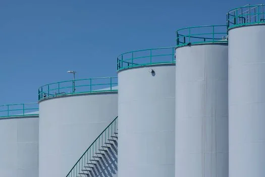
Hybrid process design for complex industrial wastewater requires integrating Dissolved Air Flotation (DAF) as a primary stage to reduce influent Total Suspended Solids (TSS) by up to 90% before it reaches the SiC membrane interface. In semiconductor and photovoltaic applications, wastewater often carries high concentrations of colloidal silica and SiC grinding particles that can overwhelm secondary treatment if not properly managed. By implementing DAF pretreatment for SiC membrane systems, engineers can remove the bulk of heavy solids (>50 μm), allowing the SiC MBR to focus on the removal of dissolved organics and sub-micron particulates.
The chemical dosing stage is vital for aggregating colloidal fines that are too small for mechanical filtration alone. Coagulants such as Polyaluminum Chloride (PAC) or Ferric Chloride (FeCl₃) are typically dosed at ranges of 50–200 mg/L, followed by anionic polyacrylamide (PAM) to form stable flocs. Once the effluent passes through the SiC MBR—utilizing submerged flat-sheet modules like the DF Series—the resulting permeate typically achieves a Silt Density Index (SDI) of less than 3. This high-quality permeate is ideal for water reclaim systems for microelectronics, where RO systems are used to achieve 70–90% water recovery for reuse in cooling towers or ultrapure water (UPW) makeup.
A 2025 photovoltaic plant design in China utilized this hybrid approach (DAF → Chemical Dosing → SiC MBR → RO) to achieve a ZLD process design for semiconductor wastewater. The system demonstrated 99.8% TSS removal and allowed the facility to reuse 95% of its process water. The process flow begins with a lamella clarifier or DAF unit to bring TSS below 50 mg/L, followed by the SiC MBR which targets BOD levels of <10 mg/L and TSS <1 mg/L. The final RO stage removes dissolved salts, ensuring the facility meets Zero Liquid Discharge (ZLD) mandates without the excessive energy costs associated with evaporative systems.
Cost Breakdown: SiC vs. Polymeric vs. Ceramic Membranes for Industrial Wastewater
Capital expenditure (CAPEX) for industrial SiC wastewater treatment systems typically ranges from $1.2M to $3.5M for flow rates of 50–500 m³/h, representing a 20–40% premium over polymeric systems that is offset by lower lifecycle operating costs. While SiC membrane modules command a higher price point—ranging from $500 to $1,500 per square meter compared to $50–$200 for PVDF—the investment is justified by the drastic reduction in operational expenditures (OPEX). SiC systems reduce energy costs by 20–40% due to lower operating pressures and decrease chemical consumption by 30–50% because the material’s hydrophobicity naturally resists organic scaling.
Maintenance labor is another significant factor in the ROI calculation. Polymeric membranes often require monthly intensive chemical cleaning (CIP) and frequent manual inspections to check for fiber breakage. SiC membranes, being rigid and chemically robust, typically require only 1 to 2 annual cleanings, reducing labor costs by 60–80%. For high-TSS applications like semiconductor wafer dicing, the ROI for a SiC system is typically realized within 3 to 5 years. This calculation accounts for the avoidance of compliance fines, reduced downtime for membrane repairs, and the extended 10-year replacement cycle compared to the 3-year cycle common for PVDF in abrasive environments.
| Cost Metric | SiC System | Polymeric (PVDF) | Ceramic (Al₂O₃) |
|---|---|---|---|
| CAPEX (500 m³/h) | $3.0M – $3.5M | $2.0M – $2.5M | $2.8M – $3.2M |
| Annual OPEX | Low (Energy/Chem Savings) | High (Replacement/Labor) | Moderate |
| Membrane Lifespan | 10–15 Years | 3–5 Years | 8–12 Years |
| Energy Use (kWh/m³) | 0.3 – 0.5 | 0.6 – 0.9 | 0.4 – 0.6 |
| Cleaning Frequency | Bi-annually | Monthly | Quarterly |
ZLD Compliance Blueprint: Pretreatment, Sludge Handling, and Regulatory Standards for SiC Systems
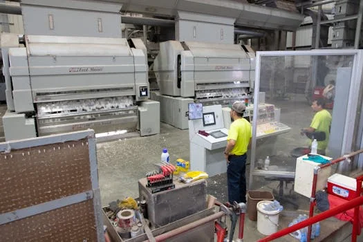
Achieving Zero Liquid Discharge (ZLD) compliance in high-tech manufacturing requires a multi-stage blueprint where SiC membrane permeate serves as high-quality feed for Reverse Osmosis (RO) systems. The first step