
What Is Known About BYD’s Szeged Wastewater Needs
UTB’s automotive and metals wastewater reference list identifies BYD at Szeged within its 2025 work involving Hungary’s lithium-ion battery and EV supply chain (UTB, 2025). The same source reports 26 delivered plants across two countries with 70,906 m³/day of combined capacity, but those are aggregate portfolio statistics—not BYD Szeged flows or treatment requirements. UTB identifies 48,000 m³/day as the capacity of its largest referenced automotive and metals plant, BAMO Technology Hungary at Ács; that figure is not attributable to BYD. No supplied source publishes BYD Szeged’s wastewater flow, pollutant profile, operating variability or dissolved air flotation duty. A defensible answer therefore begins with missing plant-specific inputs rather than an invented capacity.
Automotive and metals wastewater can contain oils, emulsions, heavy metals and surface-treatment chemistry that are not readily biodegradable. UTB’s 2025 reference approach removes these contaminants physically and chemically before biology becomes practical. BYD Szeged’s actual stream mix must therefore be established rather than inferred from the automotive sector generally.
| Published figure | Exact scope | Use for BYD Szeged sizing |
|---|---|---|
| BYD at Szeged | Identified by UTB among recent Hungarian lithium-ion battery and EV supply-chain work in 2025 | Confirms project relevance only; no flow or DAF capacity is published |
| 26 plants; two countries | UTB aggregate automotive and metals delivered reference list | Not a BYD installation metric |
| 70,906 m³/day | Combined capacity of UTB’s 26 referenced plants across two countries | Not the requirement at BYD Szeged |
| 48,000 m³/day | Capacity of UTB’s largest referenced automotive and metals plant, BAMO Technology Hungary at Ács | Not BYD Szeged capacity |
The minimum missing inputs are stream-by-stream wastewater flow, pollutant concentrations, discharge or reuse objectives and operating variability. Until those are obtained, no fixed m³/day or m³/h DAF capacity can be stated responsibly. The broader issue of wastewater handling for EV plant expansion in Hungary follows the same separation between verified site data and generic treatment assumptions.
Inputs Needed Before a BYD DAF Capacity Can Be Calculated
Request segregated flow data before combining plant streams. Relevant streams include vehicle painting, coating, body pretreatment, machining, equipment cleaning, cooling-water blowdown, sanitary sewage and stormwater. A single plant total can conceal short-duration discharge peaks and increase DAF hydraulic loading unnecessarily. HydropureWater’s 2026 sizing guidance calls for the 85th-percentile daily flow as the design basis, with brief excursions above the hydraulic-loading limit accepted (HydropureWater, 2026).
For every candidate DAF stream, obtain TSS, FOG, oil and grease, metals, pH and temperature, together with the applicable discharge or reuse specification and measured flow variability. Chemical characteristics determine whether coagulation and flocculation can create floatable floc; they are not secondary inputs to a flow calculation.
HydropureWater’s catalogue envelope assumes TSS no greater than 1,000 mg/L and FOG no greater than 500 mg/L. Wastewater outside that envelope requires recalculation rather than catalogue selection. HydropureWater’s 2026 guidance treats wastewater above 2,000 mg/L TSS as a high-strength case requiring a 20–30% hydraulic-loading safety margin and a target of approximately 2.5–3.5 gpm/ft² (HydropureWater, 2026).
| Required input | Procurement question | Why it affects DAF sizing |
|---|---|---|
| Segregated flow records | What are the daily flow distribution, 85th percentile and peak durations for each stream? | Sets design flow, equalization need and hydraulic area |
| TSS and FOG | What are measured concentrations, including excursions? | Sets solids load and whether the catalogue envelope applies |
| Oil and grease and metals | Are these free, emulsified or particulate contaminants? | Determines pretreatment and chemical-conditioning requirements |
| pH and temperature | What are operating ranges and minimum temperatures? | Influences coagulation and saturator-pump duty |
| Discharge and reuse targets | What limits apply to TSS, FOG, metals and other specified parameters? | Defines required performance rather than catalogue throughput |
Before final equipment sizing, conduct an on-site pilot using real plant effluent. UTB describes on-site pilots on real effluent before plant sizing as part of its engineering practice (UTB, 2025). The DAF system engineering specifications for 2026 provide the preliminary bands, but pilot data and final chemistry should confirm them for BYD.
How Flow, TSS and Hydraulic Loading Determine DAF Capacity
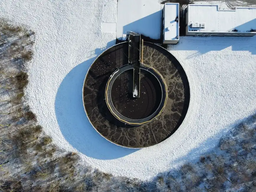
DAF surface area is calculated as design flow divided by hydraulic loading rate, with flow and area units kept consistent. This is only the first step: TSS mass load, recycle duty, air-to-solids ratio and retention time must also close. HydropureWater’s 2026 sizing guidance identifies a 3–5 gpm/ft² hydraulic-loading band, 0.005–0.060 lb air per lb TSS, 10–30 minutes retention and a 20–50% recycle ratio (HydropureWater, 2026).
For an illustrative—not BYD-specific—case, HydropureWater uses 200 gpm at 800 mg/L TSS and a hydraulic loading rate of 4 gpm/ft². The resulting area is approximately 50 ft². HydropureWater’s 2026 guide also gives the conversions as approximately 45 m³/h for 200 gpm and 4.65 m² for 50 ft². This calculation demonstrates the method; it does not establish BYD’s flow, contaminant load or required DAF size.
- Select the design flow. Use the verified 85th-percentile daily wastewater flow for each stream entering the DAF.
- Calculate the hydraulic area. Apply A = Q / L, converting both flow and loading rate to the same units.
- Check solids loading. Convert TSS concentration and flow into an hourly TSS mass load, then compare the required air mass with the 0.005–0.060 lb air per lb TSS band.
- Check contact-zone duty. Confirm that recycle flow lies within the 20–50% band and that the design provides 10–30 minutes retention.
- Check pressure and temperature. HydropureWater specifies 60–80 psig typical saturator discharge for the stated recycle system.
| Design check | HydropureWater 2026 basis | Calculation or decision required |
|---|---|---|
| Hydraulic loading | 3–5 gpm/ft² | Design flow divided by selected loading rate |
| High-strength loading | Approximately 2.5–3.5 gpm/ft² with a 20–30% safety margin above 2,000 mg/L TSS | Recalculate rather than applying the standard band |
| Air-to-solids ratio | 0.005–0.060 lb air per lb TSS | Compare available dissolved-air mass with influent TSS mass load |
| Retention time | 10–30 minutes | Check effective contact time, including any floc tube or reaction tank |
| Recycle ratio | 20–50% | Calculate recycle flow and confirm pump and saturator capacity |
| Saturator discharge | 60–80 psig typical | Include in pump, air system and utility design |
For high-strength wastewater, apply the lower hydraulic-loading band with the stated margin. A larger saturator cannot compensate for poor coagulation: HydropureWater’s 2026 guidance treats the air-to-solids requirement as an output of upstream chemistry and flotation conditions. A low calculated air demand should prompt checks of recycle pressure and recycle-pump delivery, not an automatic reduction in air supply.
Selecting a Standard DAF, Parallel Trains or a Custom Tank
A catalogue model is appropriate only after calculated area, recycle duty, contaminant envelope and site constraints fit the manufacturer’s verified model data. HydropureWater’s 2026 catalogue boundary covers 4–300 m³/h across 13 standard models; this is an equipment envelope, not BYD’s required flow. The industrial dissolved air flotation system selection should therefore follow the sizing calculation and influent characterization.
| Architecture | Applicable condition | Main engineering issue |
|---|---|---|
| Standard catalogue model | Calculated flow, area, recycle duty and contaminant envelope fit the verified model | Confirm site utilities, controls and chemical scope |
| Parallel catalogue trains | Flow exceeds 300 m³/h and the influent is sufficiently characterized for identical operation | Engineer an inlet manifold for equal loading |
| Custom rectangular tank | Flow exceeds 300 m³/h, variable loading or site layout makes parallel skids unattractive | Define tank geometry, scraper system, hydraulics and controls |
For flows above 300 m³/h, compare parallel catalogue trains with custom fabrication. Parallel trains require an engineered inlet manifold that prevents one unit from becoming overloaded while another is underloaded. They also require separate saturators, recycle pumps and chemical-dosing packages. A custom tank may reduce that duplication and provide one scum-scraping mechanism, but it transfers more design responsibility to the supplier.
Automatic chemical dosing is part of the sizing dependency, not an accessory to add later. Coagulation and flocculation affect DAF capture and air demand; the equipment proposal should therefore include an automatic chemical dosing skid and define its duty, controls and chemical storage interfaces.
Where DAF Fits in BYD’s Hungarian Treatment Train
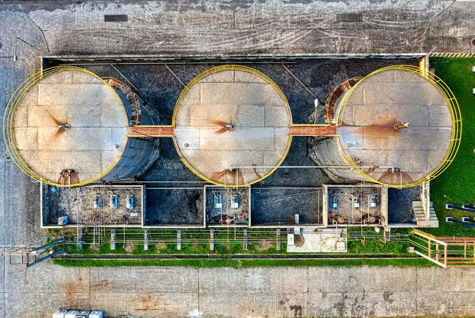
DAF should be selected as one unit within a complete treatment train, not as an isolated tank. UTB’s 2025 reference approach for automotive and metals wastewater uses coagulation, lamella separation and DAF to remove oil and metals before biological treatment. It adds membranes where reuse-grade water is required and vacuum distillation where the loop must be closed to zero liquid discharge (UTB, 2025).
These process boundaries matter. DAF is intended to remove floatable oils, FOG and suspended solids; it does not replace downstream biological COD removal or the polishing needed for reuse. The influent entering DAF must therefore match the selected upstream separation and coagulation process, the downstream biological treatment, and the final discharge or reuse specification.
Stream segregation should precede treatment design. Sanitary sewage, stormwater and process wastewater have different hydraulic and contaminant characteristics. Combining them can inflate DAF flow without improving treatment, while discharging an oily paint or coating stream directly into the general wastewater system can overload the physical pretreatment stage.
The treatment-train decision follows the intended water outcome:
- Industrial pretreatment: coagulation, flocculation, oil and solids separation, then DAF where the verified TSS and FOG envelope supports it.
- Biological treatment: apply after physical and chemical pretreatment has made the influent biologically manageable.
- Reuse: assess membrane treatment where the required water quality supports it.
- Zero liquid discharge: assess vacuum distillation and associated concentrate management when the project objective requires loop closure.
Pilot testing and permit review are prerequisites for final selection. They establish whether the selected process train achieves the required solids, FOG and metals removal under real BYD wastewater conditions. The reuse sequence may include an MBR integrated wastewater treatment system or an industrial reverse-osmosis water purification system, but neither can substitute for missing influent data or pilot confirmation.
Build a Vendor-Comparable Capacity and RFQ Package
Issue every supplier the same design-basis schedule and require each quotation to expose its calculations. A common schedule prevents vendors from comparing different flow definitions, contaminant envelopes and performance claims.
- Specify segregated flows, the 85th-percentile daily flow, peak-flow rules and operating hours.
- Specify TSS, FOG, oil and grease, metals, pH, temperature, discharge limits and reuse targets.
- Require hydraulic loading rate, required DAF area, retention time, recycle flow, recycle pressure, calculated air-to-solids ratio and expected TSS removal.
- Request confirmation of catalogue limits, parallel-train balancing, custom-tank design, controls scope and site utility requirements.
- Require a defensible summer saturator-pump assessment when influent is unheated.
| RFQ item | Supplier response required | Buyer check |
|---|---|---|
| Hydraulic capacity | Design flow, hydraulic loading rate and calculated area | Recalculate from the stated inputs |
| Solids removal | Expected TSS removal with the defined influent and conditioning | Compare with the treatment objective, not another vendor’s guarantee |
| Recycle and air | Recycle flow, pressure and calculated air-to-solids ratio | Check pump, saturator and air-system consistency |
| Equipment architecture | Catalogue model, balanced parallel trains or custom tank | Confirm envelope, redundancy, controls and site access |
| Temperature duty | Summer saturator-pump assessment for unheated influent | HydropureWater identifies a 10–15% derate as defensible for this condition (HydropureWater, 2026) |
HydropureWater’s 2026 guide reports 92–97% TSS removal for a correctly conditioned 200 gpm, 800 mg/L TSS example. Require suppliers to explain how their proposed configuration meets the applicable objective, but do not carry that example into the BYD RFQ as a guaranteed performance value. Hydraulic sizing, contaminant treatment and equipment selection must be shown on the same basis in every response. The industrial dissolved air flotation system offer should therefore be accompanied by the calculation schedule rather than a model reference alone.
Frequently Asked Questions
What DAF flow capacity is required for BYD’s EV plant in Hungary?
No defensible fixed capacity can be stated from the supplied public evidence. Obtain BYD’s stream-by-stream flow records and calculate from the 85th-percentile daily flow, TSS load and treatment objectives. The 70,906 m³/day and 48,000 m³/day figures in UTB’s 2025 reference list have different portfolio and plant scopes and must not be presented as BYD Szeged requirements.
Can a 45 m³/h DAF be selected from the example used in HydropureWater’s sizing guide?
Not for BYD from the example alone. HydropureWater’s 2026 guide uses 200 gpm, approximately 45 m³/h, at 800 mg/L TSS to demonstrate roughly 50 ft², approximately 4.65 m², at 4 gpm/ft². It is an illustrative calculation. A 45 m³/h selection becomes defensible only if BYD’s verified flow, contaminant envelope, recycle duty and site constraints support it.
Which data should I request from BYD before comparing DAF suppliers?
Request segregated flow records; the 85th-percentile daily flow; TSS, FOG, oil and grease, metals, pH and temperature; flow variability; and applicable discharge or reuse limits. Require the same data schedule from every bidder so that quotations are technically comparable.
When are parallel DAF trains or a custom tank preferable to a standard catalogue unit?
For flows above 300 m³/h, compare parallel catalogue trains with custom fabrication. Parallel trains require engineered flow distribution and duplicate saturators, recycle pumps and dosing packages. A custom tank may suit variable influent, footprint constraints or a preference for one scum-scraping mechanism; its hydraulic design responsibility must be explicit in the RFQ.
What compliance risk arises if the DAF is sized from average flow without pilot testing?
Average-flow sizing can leave the unit hydraulically overloaded during sustained peak periods or oversized during normal operation, while omitting the effects of real TSS, FOG and coagulation demand. HydropureWater’s 2026 guidance identifies the 85th-percentile daily flow as the design basis and UTB’s 2025 practice includes testing real effluent before plant sizing. Final permit compliance still requires site-specific data, pilot evidence and review of the applicable discharge specification.