
Determine Which Limits Apply Before Designing Equipment
40 CFR Part 433 covers metal-finishing operations, including forming, finishing, forging, foundry, metal-spraying and machining-wash operations co-located with plating or anodizing lines; a plant that only stamps dry parts and sends them to a separate finisher is generally outside that scope (HydropureWater, 2026). Applicability must therefore be established from actual operations, not the company description. Existing sources are evaluated against PSES, while new sources are evaluated against PSNS; the governing design target is the stricter applicable requirement for each pollutant, including POTW local limits. Before purchasing equipment, obtain the current local-limit table, industrial sewer-use permit, discharge authorization and any Connecticut requirements. See the related pretreatment-limit selection guide for the same permit-first method.
The regulatory review should produce a parameter-by-parameter design envelope rather than a single generic “pretreatment limit.” Part 433 addresses cadmium, chromium, copper, lead, nickel, silver, zinc and total toxic organics. POTW limits may also control oil and grease, total suspended solids and pH (HydropureWater, 2026). For each parameter, record the categorical standard, whether PSES or PSNS applies, the POTW local limit, the proposed control point and the required monitoring frequency. A facility near Simsbury should not assume that an older federal table or a standard construction drawing establishes the current discharge requirement.
| Decision point | Regulatory or operating test | Engineering consequence |
|---|---|---|
| Categorical scope | Are plating, anodizing or hard-chrome operations operated on site, or co-located with covered metal-finishing operations? | Apply Part 433 requirements if covered; otherwise document the basis for exclusion. |
| Source status | Existing source or new source? | Compare PSES and PSNS limits with the current POTW table. |
| Receiving sewer | What local limits and discharge conditions apply at the receiving POTW? | Use the stricter applicable limit for each parameter. |
| Process scope | Does the plant generate cyanide, Cr(VI), oils, dissolved metals or elevated TSS? | Define the treatment units and control strategy before equipment selection. |
| Approval documents | Are the sewer-use permit, local limits, discharge authorization and state requirements current? | Freeze the design basis only after document review. |
Characterize the Wastewater Before Sizing the Treatment Train
A full week of composite influent sampling is necessary before sizing equalization because plating shops produce batch dumps rather than steady flow; a four-hour composite can miss a Friday-afternoon dump and undersize the basin (HydropureWater, 2026). The same source reports screening ranges from its 2026 field data: oils at 50–500 mg/L, total dissolved metals at 5–200 mg/L, TSS at 100–1,000 mg/L, and pH moving between 2 and 12 across batch dumps. Those values are screening information, not substitute site data or a universal design basis.
Build the sampling program around every process contributor. Stamping, machining and drawing compounds can carry oils; acid pickling can release dissolved metals; chromic-acid anodizing and hard chrome can contribute Cr(VI); conversion coating, grinding swarf and casting sand can add suspended solids. If alkaline cyanide plating remains in service, identify whether zinc, copper, cadmium or silver plating chemistry is present, because cyanide must be destroyed before metals precipitation (HydropureWater, 2026).
- Request pH, flow, oil and grease, total metals and dissolved metals results.
- Add Cr(VI) and cyanide testing wherever the process inventory indicates those contaminants.
- Measure TSS and conductivity across production and dump periods.
- Separate analytical results from supplier field experience in the design report.
The mass-loading calculation should use measured flow and concentration data, not concentration alone. Composite records should identify whether the sample included tank dumps, line washdown, floor drainage and production rinsewater. That distinction determines whether equalization is a short-flow buffer or the central control unit for a variable, batch-discharge stream.
Build a Treatment Train for Each Contaminant
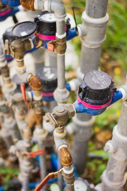
Each contaminant requires a different control mechanism, and upstream failure carries into every downstream unit. The treatment sequence starts with equalization, followed by oil removal, Cr(VI) reduction, cyanide oxidation, metals precipitation, solids separation, final pH adjustment and sludge handling (HydropureWater, 2026).
- Equalize flow and pH. Batch discharges must be blended before feed pumps and chemical controls respond to sharp changes.
- Remove oils. Physical separation or chemical break addresses free and emulsified oils before they interfere with floc formation and flotation.
- Reduce Cr(VI). Sodium metabisulfite or ferrous sulfate reduction is performed at pH 2–3, with ORP controlled at roughly 250–300 mV; the resulting trivalent chromium can then precipitate as Cr(OH)₃ at pH 8.5–9.5 (HydropureWater, 2026).
- Oxidize cyanide. Cyanide destruction precedes metals precipitation because unresolved cyanide can resolubilize downstream precipitates (HydropureWater, 2026).
- Precipitate and separate metals. Controlled pH adjustment forms metal hydroxides, which are removed in a DAF or lamella clarifier.
- Trim and verify. Final pH is adjusted to the POTW requirement, followed by permitted monitoring and controlled sludge dewatering.
The automatic chemical dosing system should meter reductant, oxidant, pH-adjustment chemicals and polymer against both flow and treatment feedback. A metalworking wastewater DAF system can remove hydroxide floc and other floatable solids after the chemistry is complete.
| Contaminant or objective | Required unit operation | Operating control | Primary failure mode | Verification evidence |
|---|---|---|---|---|
| Batch flow and pH peaks | Equalization basin | Level and flow control | Oversized batch reaches downstream chemistry | Basin level trend and composite sampling |
| Free or emulsified oil | Oil removal or chemical break | Oil concentration and pH | Interference with floc and flotation | Oil-and-grease analysis |
| Hexavalent chromium | Reduction, then precipitation | Reductant feed, pH 2–3 and ORP | Incomplete reduction or chromium remains soluble | Cr(VI) and total chromium results |
| Cyanide | Oxidation | Oxidant feed and process pH | Metal precipitates redissolve downstream | Cyanide analysis |
| Dissolved metals | pH-controlled precipitation | pH and mixing | Precipitate carryover or incomplete removal | Total and dissolved metals |
| Suspended solids | DAF or lamella clarification | Hydraulic loading, floc condition and recycle | Floc breakthrough or fragile float | TSS and operating trend data |
| Metal sludge | Controlled dewatering and disposal | Solids feed and press-cycle control | Chemical carryover, wet disposal or equipment blockage | Dry-solids record and disposal manifest |
Select DAF or Lamella Clarification for Solids Separation
DAF is the better starting point when the objective includes suspended solids, FOG, oil and grease or colloidal material; lamella clarification is attractive where compact inclined-plate separation, sludge recirculation and integrated flocculation suit the installation (HydropureWater, 2026). The hydraulic and floc properties of the actual wastewater—not available floor area alone—should decide between them. A detailed DAF versus clarifier comparison for fabricated metals wastewater provides an additional decision framework.
For DAF design, HydropureWater’s 2026 guidance identifies hydraulic surface loading of 4–20 m/h depending on model and floc density, an air-to-solids ratio of 0.005–0.060 with 0.02 as a typical design point, and recycle of 10–30% of forward flow. Increasing the air-to-solids ratio can produce drier float but consumes more blower power and may break fragile floc. Increasing recycle can improve TSS removal but dilutes the chemistry and increases equalization demand. These relationships should appear in the supplier’s sizing calculation rather than only in a model-selection sheet.
| Selection issue | DAF | Lamella clarification |
|---|---|---|
| Primary fit | Suspended solids, FOG, oil, grease and colloidal matter | Compact solids separation where integrated flocculation and sludge recirculation suit the waste |
| Key design variables | Surface loading, air-to-solids ratio and recycle | Clarifier area, plate configuration, flocculation and sludge withdrawal |
| Main operating risk | Fragile floc, excessive recycle or unequal air transfer | Floc disturbance, carryover and uneven sludge collection |
| Upstream protection | Screen rags, wipes and tramp metal before flotation or sludge equipment | Use the same upstream protection to prevent blinding and blockage |
Rags, wipes and tramp metal should be removed before the sludge train because they can prematurely blind a filter press (HydropureWater, 2026). The equipment proposal should show a protected route from collection to equalization, chemical reaction, solids separation and dewatering.
Control Chemical Dosing, Sludge and Compliance Risk
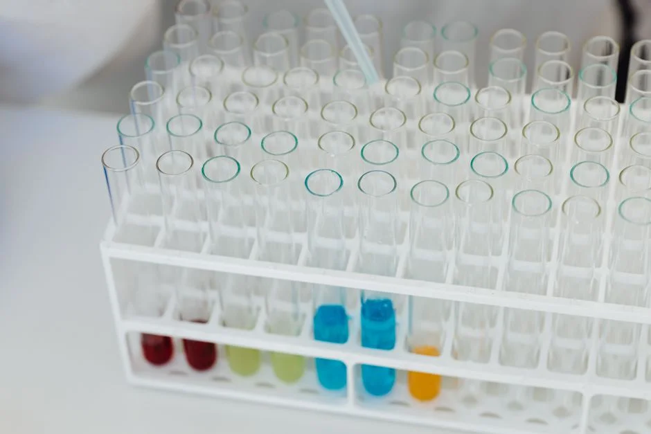
Reliable pretreatment depends on feedforward chemical dosing combined with feedback from pH or ORP; fixed manual pump settings do not control a batch-discharge stream (HydropureWater, 2026). The control narrative should specify how flow-paced feeds respond to equalized flow and how pH or ORP feedback corrects chemical demand. PLC-controlled, skid-mounted systems permit bench testing and interlock verification before shipment, while a single operator interface reduces the number of independent panels that must be managed.
Each metering pump should include a calibration column and stroke-count totalizer so operators can verify chemical delivery. Interlocks for pH excursion, out-of-range ORP and high TSS should automatically divert flow to the equalization header instead of allowing an upset to reach the sewer. These controls are part of the compliance case because they identify both the initiating event and the protective action (HydropureWater, 2026).
For metal-hydroxide sludge, HydropureWater’s 2026 benchmarks are 2–5% dry solids leaving a DAF and 25–35% after plate-and-frame dewatering. The same source notes a belt-press ceiling around 22% for this sludge type. A metal hydroxide sludge filter press should therefore be evaluated against the disposal contract and transport method, not against filter area alone. Hauler acceptance, leachate characteristics and destination requirements must be confirmed before selecting the dewatering target.
Performance verification should include composite sampling against the current permit, applicable PSES or PSNS parameters, and the stricter POTW local limits. Keep chemical-use records, pump totals, ORP and pH trends, alarm events, equalization levels, TSS results and sludge-disposal records with each compliance review.
Plan for Future Polishing Without Overbuilding Now
Most fabricated metals plants can meet sewer limits with the core treatment train and do not require polishing (HydropureWater, 2026). Polishing becomes relevant when the POTW tightens a local limit, the plant establishes a reuse objective or a new requirement creates a treatment objective not addressed by the primary train.
For BOD/COD tightening or reuse, HydropureWater’s 2026 guidance describes a submerged PVDF MBR with filtration below 1 μm. For sub-ppm TDS or very tight metal targets, reverse osmosis is appropriate, with upstream multi-media filtration protecting the membranes. The guidance also states that EPA’s 2026 PFAS rulemaking activity scoped to chrome-finishing facilities did not establish a current numerical PFAS limit for chrome finishers. PFAS should therefore remain a monitored contingency, not a numeric design basis.
Reserve space, utilities, containment and control interfaces for a future anion-exchange or granular activated carbon polish skid. The integrated MBR treatment concept should be evaluated for a defined reuse or tightening objective, not installed simply because future polishing is possible.
Use a Compliance-First Equipment Purchasing Checklist
A supplier should not guarantee outlet performance until it has identified the governing POTW local-limit table and the applicable categorical standard. Require a complete process flow, equipment-sizing basis, chemical-consumption range, control narrative, alarm list and solids-disposal plan. The equalization basis must reflect at least a full week of representative composite sampling rather than a short spot sample, because a four-hour composite can miss a batch dump and undersize the basin (HydropureWater, 2026).
- Verify the selected PSES, PSNS and local-limit comparison for every regulated parameter.
- Review DAF or clarifier selection against measured batch flow, floc properties and treatment objectives.
- Confirm that dosing, equalization, solids separation and dewatering form one controllable process.
- Check that equipment can accept a future polishing train without uncontrolled rework of the civil or control design.
- Require factory testing, pre-wiring, installation boundaries, commissioning records, operator training and ongoing compliance-verification support.
For the solids-separation scope, use the fabricated-metals DAF and clarifier decision guide to compare operating variables before accepting a model. Require the supplier to state which claims are calculated design values, which are guaranteed performance terms and which depend on site chemical consumption, sludge properties or operator practice.
Frequently Asked Questions
Is every fabricated metals plant subject to 40 CFR Part 433?
No. Part 433 applies to specified metal-finishing operations, including forming, finishing, forging, foundry, metal-spraying and machining-wash operations co-located with plating or anodizing lines. A dry-stamping operation shipping parts to a separate finisher is generally outside the category, while a facility operating its own zinc, nickel or chromic-acid tank is within the covered scope (HydropureWater, 2026). Document the plant’s actual operations before selecting categorical treatment assumptions.
Which limit table should control equipment sizing?
Build the design envelope parameter by parameter. Compare the applicable PSES or PSNS requirement with the current POTW local limit and use the stricter applicable limit for each pollutant. A POTW may also add controls for oil and grease, TSS and pH (HydropureWater, 2026). Do not accept a guarantee based on a federal table without identifying the receiving sewer’s current local-limit table.
What should a buyer request when budgeting pretreatment equipment?
Request a budgetary quotation tied to the actual process inventory, full-week composite dataset, current POTW limits, treatment objectives, chemical consumption basis, solids-disposal method and required controls. Ask the supplier to separate equipment cost from foundations, electrical work, chemical supply, commissioning, operator training, maintenance and sludge disposal. No supported research quotation was supplied, so the capital price cannot be stated responsibly; those scope inputs must be obtained before comparing bids.
How do I size a DAF versus a lamella clarifier?
Use DAF when the treatment objective includes suspended solids, FOG, oil, grease or colloidal matter; consider lamella clarification when compact inclined-plate separation, sludge recirculation and integrated flocculation fit the installation (HydropureWater, 2026). For DAF, require the supplier to show surface loading, air-to-solids ratio and recycle assumptions, including their effects on floc integrity, power use and equalization demand.