Why Pressure Probes Fail in Sewer Lift Stations
Pressure probes fail in sewer wet wells through two distinct mechanisms, and both are captured in a Gulf Coast wastewater treatment plant deployment documented by Flowline (flowline.com, 2025). Operators there said it plainly: "If we hang them from the top, the pump turbulence damages them. If we affix them to the bottom, we have to go down there to install and maintain them with a confined space team." Either way, the probe ends up either destroyed by pump cycling or buried in a confined-space service obligation — neither outcome is acceptable for a continuously running lift station.
The root cause is the wet-well contaminant cocktail itself, which the same source lists as feces, paper, grease, chemicals, particulates, and trash. A submerged sensor sits inside that medium, so the active element fouls, the diaphragm drifts, and the cable shielding corrodes. A top-suspended probe avoids burial but now lives in the pump turbulence zone, where pressure transients from each pump start slam the diaphragm until it fatigues. The result is the same either way: an instrument that the operations team has learned not to trust.
The maintenance economics are not just the sensor. Each confined-space entry is a permit, a standby team, a shutdown window, and a written entry plan. Flowline's solution for the same site was an intrinsically safe, top-mounted, non-contact radar (model LR31) that the case study describes as "easily installed at the top for maintenance-free operation" (flowline.com, 2025). The same radar "provides reliable level data to the SCADA for pump control and the sensor display provides convenient level indication" (flowline.com, 2025), so the instrument swap is a like-for-like signal change to the existing SCADA — the control system, the wiring conduit, and the tag database stay put. For readers still working through their own bulking and clarifier issues, the activated sludge bulking troubleshooting guide covers the downstream process side, while the radar retrofit fixes the upstream instrumentation.
How FMCW Radar Sees Through a Wet Well
A non-contact radar level transmitter emits a microwave signal from a top-mounted antenna toward the liquid surface and measures the reflected return. The sensor never touches the wastewater, so grease, rags, and FOG cannot coat the active element — that is the structural reason a top-mounted radar is intrinsically cleaner than any submersible probe. Frequency-Modulated Continuous Wave (FMCW) instruments sweep a band of frequencies, mix the return against the transmitted sweep, and extract a distance from the resulting beat frequency.
Radar tolerates conditions that defeat other non-contact technologies. Foam, vapor, temperature stratification, and condensation that sit in the wet-well headspace do not absorb the microwave return in the way they attenuate an ultrasonic echo. Ultrasonic transducers struggle when foam lies between the transducer and the liquid surface, and condensate on the transducer face adds to the problem; the comparison in lift-station headspace is therefore qualitative until site-specific vendor data is obtained. Guided-wave radar still requires a probe extending into the well, so the contamination vulnerability remains, only relocated to the cable and weight assembly.
Two parameters decide whether a radar will work in a particular wet well. Blocking distance is the minimum level the radar can read — the instrument is blind to liquid that rises into the antenna's near field. Beam angle determines the cone of liquid surface the radar actually sees; if the cone is wide enough to include the wet-well wall or an incoming drop pipe, the wall becomes a multipath echo and the reading wanders. Both parameters are checklist items that the spec section will resolve against the well diameter and the pump-down level. The citable definition for the article is that an "intrinsically safe radar sensor provides reliable level data to the SCADA for pump control and the sensor display provides convenient level indication" (flowline.com, 2025), which is the integration baseline the rest of this guide works against.
Radar vs Ultrasonic vs Guided-Wave vs Pressure: Selection Matrix
A specifier defending a radar choice to a procurement committee has to show what was given up and what was gained against each alternative. The table below consolidates the comparison around five questions that always come up: where the instrument mounts, whether it touches the wastewater, how it handles foam and condensation in the headspace, what maintenance access it needs, and what it takes to integrate with the existing SCADA. The radar and pressure rows are anchored to the Flowline Gulf Coast case (flowline.com, 2025); the ultrasonic and guided-wave rows are qualitative because the supplied research did not include their frequency or accuracy specifications.
| Criterion | Non-contact radar (FMCW) | Ultrasonic | Guided-wave radar (GWR) | Submersible pressure |
|---|---|---|---|---|
| Mounting location | Top of wet well, on existing nozzle | Top of wet well, on existing nozzle | Top of wet well, probe extends down into the well | Suspended from top, or anchored at bottom |
| Contact with wastewater | None — non-contact, look-down | None — non-contact, look-down | Probe is in the well; coaxial cable and weight submerged | Submerged diaphragm and cable |
| Foam / condensation tolerance | Tolerates foam, vapor, and condensate that defeat ultrasonic | Struggles with heavy foam and condensate on the transducer face | Probe end can foul with grease and rags; cable headspace tolerance similar to non-contact radar | Not applicable — sensor is below the liquid |
| Maintenance access | Top-side, no confined-space entry (flowline.com, 2025) | Top-side, no confined-space entry | Top-side, but probe extraction may require pulling a wet, fouled cable | Confined-space entry for install and service (flowline.com, 2025) |
| SCADA integration | Direct feed to SCADA for pump control, with on-sensor local display (flowline.com, 2025) | Direct feed, but readings may require filtering to suppress foam-induced dropouts | Direct feed; probe-coating compensation required in the controller | Direct feed; subject to drift and turbulence noise |
The recommendation falls out of the table. Radar is the default for new and retrofit lift stations where headroom allows the antenna to sit above the high-high level and clear the blocking distance. Ultrasonic is acceptable only in wet wells with light foam and clean headspace air. Guided-wave radar is the fallback when headroom is too tight for a non-contact antenna, but it inherits a fouling vulnerability. Pressure is the choice only when radar is cost-prohibitive and the operations team has already accepted the confined-space maintenance burden. The UV installation engineering guide covers downstream disinfection selection using the same kind of head-to-head logic.
Specifying a Lift Station Radar: Parameter Checklist
A defensible RFQ line item starts with the well geometry and works outward to the SCADA tag. The table below is the parameter set a buyer should lock down before requesting a quote; the supplier is then responsible for proving their model satisfies each one. None of these parameters require invented numeric ranges — each is a yes/no or a fit-check against the well drawing.
| Parameter | What to confirm with the supplier | Why it matters in a wet well |
|---|---|---|
| Measurement range vs wet-well depth | Radar range must cover from below the pump's lowest drawdown level to above the high-high alarm setpoint | Out-of-range readings produce flat-line SCADA and pump dry-run conditions |
| Blocking distance vs maximum pump-down level | Blocking distance must be below the lowest level the pump will draw the well to | If the well pumps into the blocking zone, the radar goes blind at the worst possible moment |
| Beam angle vs wet-well diameter | Vendor should run a beam-angle calculation against the actual well diameter and nozzle height | A wide beam picks up wall echoes and drop-pipe echoes, generating false readings |
| Process connection vs existing nozzle | Flange or thread must match the existing top-of-well nozzle, or a coupling is required | Drilling a new nozzle is a confined-space task and should be avoided when possible |
| IP rating vs hosing environment | IP66/IP67 minimum for a hosed-down lift station | The radar is above the wet well but still inside the chamber |
| Hazardous-area classification | Intrinsically safe certification for the sewer atmosphere (methane) | The LR31 in the Flowline case is explicitly described as intrinsically safe (flowline.com, 2025) |
| Signal output | 4–20 mA + HART, or Modbus/IO-Link, matched to existing SCADA | The radar in the Flowline case "provides reliable level data to the SCADA for pump control" (flowline.com, 2025) — the new instrument must drop into the same loop |
Two pre-installation checks belong on the supplier call. First, confirm whether the well is a stilling well or an open well, because a stilling well changes the effective diameter seen by the beam. Second, walk the site and note foam presence, splashing from pump cycling, and condensate on the lens — each of these changes model selection but none require a numeric range to decide.
Installation at the Top of the Wet Well
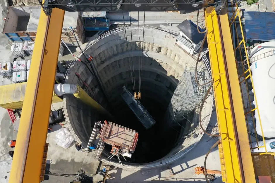
The top-mount workflow is consistent with the Flowline Gulf Coast deployment, where the radar "is easily installed at the top for maintenance-free operation" (flowline.com, 2025). The instrument mounts on an existing nozzle or a new coupling at the top of the wet well, aimed perpendicular to the liquid surface, with the display visible from the hatch so an operator can read the level without entering the chamber. No confined-space entry is required for install, calibration, or routine inspection — that is the structural fix for the maintenance burden the same case study documents for pressure probes.
Cable routing and surge protection follow the same intrinsically safe wiring practices already used for the SCADA loop the radar is replacing. The instrument is a like-for-like signal swap, so the conduit, the junction box, and the SCADA terminal block do not move; the only change is the device at the top of the well and the calibration constants in the SCADA tag. A commissioning step belongs at the end: compare the radar reading against a hand tape across the full pump cycle, from high-high to pump-off, to confirm the level-to-SCADA mapping is correct before the station is handed back to operations. This check is the difference between a radar that the operations team trusts on day one and one that gets bypassed after the first bad reading. Readers planning a wider site retrofit can review the data center cooling blowdown treatment guide for an example of phased instrumentation rollout.
Reusing the Radar Signal for Sewer Blockage Detection
The same continuous level signal that drives pump control can also drive sewer blockage detection, turning the radar into a network-health asset as well as a pump-control instrument. A peer-reviewed study in Processes established the threshold and the success rates (MDPI, 2023-01). Within four minutes of a blockage in a DN150 pilot pipe, the upstream liquid level rose to a peak that was 300% to 700% higher than the pre-blockage baseline — a signature the existing SCADA can alarm on without any new hardware, just a new tag and a rate-of-change calculation.
The same study documents the spatial reach. "A single liquid level sensor can at least complete the blockage identification of the sewer with a total of 65 m upstream and downstream," and a network of sensors extends that range further (MDPI, 2023-01). The success rates are explicit: in the DN150 pilot, 96% of blockage identifications across 150 monitoring groups at 0.5–5 m³/h flow were completed using the two conditions of liquid level change rate and change range, and the identification rate within 4 m upstream of the blockage point was 95.3% (MDPI, 2023-01). In the DN300 full-scale trial, 83.3% of post-blockage cases were successfully identified with an overall success rate of 95.6% (MDPI, 2023-01).
The false-positive rate is the caveat. In the DN200 pilot, 19.4% of normal-operation data was misjudged as blockage, so alarm thresholds must be tuned per site rather than copied from the paper, and 20% of blockages in the same pilot were misjudged as normal operation, giving an 80% pilot success rate (MDPI, 2023-01). The implication for the specifier is that the blockage alarm is a trending tool, not a binary trip — it should page the operations team for investigation, not shut the station down. The 2026 sewer pretreatment compliance guide covers the regulatory side of network monitoring for industrial sites.
Integrating Radar Level with Lift Station SCADA and Alarms
The radar output maps to standard lift-station SCADA tags: level (engineering units), high-high alarm, low-low alarm, pump-start setpoint, pump-stop setpoint, and a new blockage-trend alarm built from the 300%–700% rise-in-four-minutes rule documented in the Processes study (MDPI, 2023-01). The blockage alarm is a rate-of-change tag, not a level tag — it fires when the level rises faster than the normal wet-well fill curve, which is a different calculation than the high-high level trip.
Redundancy matters even with a non-contact radar. The Flowline case study gave operators a local fallback through the on-sensor display, which "provides convenient level indication" (flowline.com, 2025); the same philosophy extends to a float switch as a high-high backup in the SCADA. Data logging at 1-minute resolution is sufficient to capture the 4-minute blockage signature documented in the Processes study (MDPI, 2023-01); faster logging is unnecessary and just consumes SCADA bandwidth. The handoff at commissioning is the part that gets skipped: the radar tag map, the alarm setpoints, and the blockage-trend thresholds should be passed to the operations team in writing before the station goes live, not after the first false page.
Frequently Asked Questions
What blocking distance and beam angle do I need for a typical wet well?
Blocking distance must be below the pump's lowest drawdown level so the radar does not go blind when the well is pumped down, and beam angle must be narrow enough that echoes from the wet-well wall sit outside the measurement zone. Exact figures vary by vendor and were not present in the supplied research, so request a vendor beam-angle calculation against your specific well diameter and nozzle height before ordering.
Can a radar level transmitter replace a submersible pressure transducer without changing my SCADA?
Yes. The Flowline Gulf Coast deployment replaced pressure sensors with a top-mounted, intrinsically safe radar (LR31) that "provides reliable level data to the SCADA for pump control" (flowline.com, 2025), with the on-sensor display as a local fallback. The change is on the instrument side of the loop — the SCADA tag, the wiring, and the control logic stay put.
Will grease, foam and rags in the wet well blind a radar sensor?
Radar is non-contact and mounted at the top, so the active element stays out of the wet-well contaminant cocktail (feces, paper, grease, chemicals, particulates, trash) described in the Flowline case (flowline.com, 2025). Foam and condensate may slightly extend the effective blocking distance but do not coat the lens, because the lens is above the liquid surface.
How much does a lift-station-grade radar level transmitter cost in 2026, and what drives the budget?
The supplied research does not include radar price points, so a numeric budget cannot be quoted here. The buyer should request a line-item quote that separates the instrument, an intrinsically safe rated cable and surge protection, a top-of-well nozzle or coupling, and SCADA tag commissioning, and should confirm whether calibration and commissioning labor are included in the quote or billed separately.
What should I ask a radar supplier to confirm suitability before I buy?
Request the vendor's wet-well beam-angle calculation against your specific well diameter and nozzle height, written confirmation of hazardous-area certification for the sewer atmosphere, signal-output compatibility with the existing SCADA tags, and a documented mean-time-between-failure figure for the model being quoted. Each of these is a verifiable input, not a marketing claim.
Related Equipment
- rotary mechanical bar screen — specifications, capacity range, and technical data
- automatic chemical dosing system — specifications, capacity range, and technical data