Why Integrated Systems Fail: Beyond Simple Overload
Integrated wastewater treatment units are engineered as interdependent ecosystems where mechanical, biological, and control failures often cascade into total system non-compliance. Unlike sprawling municipal facilities, compact systems like a compact underground A/O system for residential and industrial use rely on high biomass concentrations within small footprints, meaning they lack the hydraulic buffer to absorb significant operational deviations. When a single component fails—such as a primary screen clogging—the resulting flow restriction can cause pump cavitation, which subsequently starves the biological reactor of consistent influent, leading to a collapse of the microbial population (Zhongsheng field data, 2025).
Space constraints in integrated designs strictly limit surge capacity, often making them vulnerable to hydraulic washouts. Engineering data suggests that sustained flow exceeding 110% of the rated capacity—for instance, pushing more than 88 m³/h through an 80 m³/h WSZ unit—will lead to the physical washout of active biomass, particularly in the aerobic stage. This loss of Mixed Liquor Suspended Solids (MLSS) can take weeks to recover, during which time effluent quality will remain below regulatory standards. the high level of automation in these units can be a double-edged sword; while it reduces manual labor, it often masks early warning signs. Operators who fail to monitor real-time trends in Dissolved Oxygen (DO) or pH may miss the gradual decline of nitrifying bacteria until the system reaches a tipping point of failure.
Environmental factors also play a disproportionate role in integrated system stability. Because these units are often installed in sub-grade or compact enclosures, thermal retention can vary. A drop in wastewater temperature to below 12°C can reduce the metabolic rate of nitrifiers by 50%, a factor that must be compensated for by increasing the Sludge Retention Time (SRT). Without these proactive adjustments, the integrated system’s "black box" nature leads to a reactive maintenance cycle that increases downtime and operational costs.
Poor Effluent Quality: When Discharge Limits Are Exceeded
Total Suspended Solids (TSS) exceeding 15 mg/L in the final effluent is frequently a result of clarifier sludge blanket mismanagement, where a depth greater than 60 cm indicates poor settling characteristics. This is often driven by filamentous bulking, a condition common in low Food-to-Microorganism (F/M) ratio A/O systems where the sludge does not compact efficiently. To diagnose this, operators must perform a 30-minute settleability test; if the Sludge Volume Index (SVI) is above 150 mL/g, the biomass is likely dominated by filamentous organisms that resist gravity settling. Immediate corrective action involves adjusting the Return Activated Sludge (RAS) rate to stabilize the blanket depth at 30–45 cm.
When effluent Chemical Oxygen Demand (COD) rises above 100 mg/L, it typically points toward either inadequate aeration or an influent toxic shock. For standard integrated biological units, maintaining a DO concentration of 2.0 to 4.0 mg/L in the aerobic zone is critical for the oxidation of organic matter. If the influent COD spikes above 500 mg/L—a common occurrence in industrial batches—the oxygen demand may exceed the blower's capacity, leading to anaerobic pockets. ammonia nitrogen spikes exceeding 5 mg/L are a primary indicator of nitrifier inhibition. This can be caused by residual chlorine levels as low as 0.1 mg/L or a pH shift outside the 7.0 to 8.5 range. Operators should implement troubleshooting steps for small medical facilities with automated systems to ensure that chemical disinfectants from upstream processes are not neutralizing the biological treatment stage.
| Effluent Parameter | Compliance Threshold | Diagnostic Indicator | Primary Corrective Action |
|---|---|---|---|
| TSS (Total Suspended Solids) | >15 mg/L | Sludge blanket >60 cm | Increase Waste Activated Sludge (WAS) rate by 10% |
| COD (Chemical Oxygen Demand) | >100 mg/L | DO <2.0 mg/L in aerobic tank | Increase blower frequency; check for toxic influent |
| NH3-N (Ammonia Nitrogen) | >5 mg/L | Influent Temp <12°C or pH <7.0 | Adjust SRT to 20+ days; add alkalinity (sodium bicarbonate) |
| Total Phosphorus (TP) | >1.0 mg/L | Poor anaerobic release | Optimize PAC/FeCl3 dosing; check anaerobic ORP <-150mV |
Sludge Bulking and Foaming: Biological Imbalance Fixes
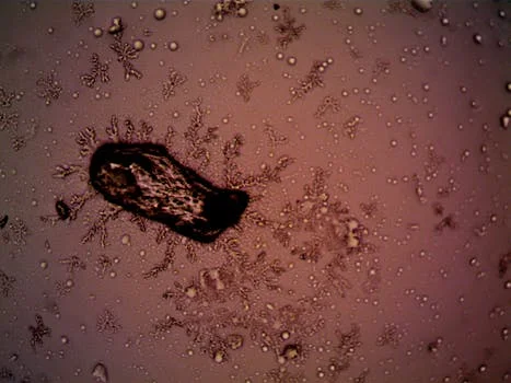
Filamentous sludge bulking, characterized by an SVI greater than 150 mL/g, occurs most frequently when the F/M ratio drops below 0.2, creating a competitive advantage for long-chain bacteria. In integrated A/O systems, this imbalance prevents the sludge from settling in the secondary clarifier, leading to "cloudy" effluent and biomass loss. To restore balance, operators should increase the waste sludge rate by 15–20% to reduce the overall sludge age, or utilize a RAS booster pump to increase the return rate, thereby increasing the F/M ratio in the contact zone. According to EPA guidelines, maintaining a BOD:N:P ratio of 100:5:1 is essential to prevent nutrient-deficiency-induced bulking.
Biological foaming is another common symptom of microbial distress in compact systems. The presence of thick, white, viscous foam is a classic sign of Microthrix parvicella overgrowth, which thrives in high-grease environments with long sludge ages. The fix involves reducing the SRT to less than 10 days and increasing DO levels to above 3 mg/L to "out-compete" these specialized bacteria. Conversely, grey or scummy foam suggests the presence of anaerobic pockets within the aerobic zone. This is often caused by uneven air distribution; operators must inspect diffuser alignment and ensure a mixing velocity of at least 0.3 m/s in anoxic zones to prevent solids from settling and fermenting. Implementing science-backed methods to reduce fouling and extend membrane life can also help in MBR-integrated systems where foam can interfere with level sensors and membrane scouring.
Pump and Aeration System Failures
Submersible pump cavitation in integrated plants occurs when the Net Positive Suction Head (NPSH) available is lower than the NPSH required by the pump, often due to clogged intake screens or excessive lift requirements. In a typical WSZ unit, if the static head is less than 2 meters or the inlet screens are blocked by debris, flow rates can drop by 30–50%, leading to internal turbulence and impeller damage. Operators should verify that the inlet screen mesh is clear of "ragging" and that the pump is not operating too far to the right of its performance curve. If cavitation persists, lowering the pump elevation or increasing the suction pipe diameter may be necessary.
Aeration failures are often more subtle, manifesting as low DO despite blowers running at maximum frequency. This is frequently caused by membrane diffuser fouling, where calcium carbonate scale or biological slime blocks the pores. A pressure drop exceeding 25 kPa across the aeration manifold is a definitive indicator of clogging. To resolve this without system drainage, a 2% citric acid solution can be injected into the air lines monthly to dissolve mineral scale. If air binding occurs in the centrifugal pumps—common after maintenance cycles—the pump chamber must be manually primed and air vented from the highest point in the discharge line to restore head pressure.
| Mechanical Symptom | Probable Cause | Technical Threshold | Immediate Fix |
|---|---|---|---|
| Pump Vibration/Noise | Cavitation | NPSHa < NPSHr | Clean inlet screens; check static head >2m |
| Low Airflow/High Pressure | Diffuser Fouling | Backpressure >25 kPa | In-situ cleaning with 2% citric acid |
| Motor Overheating | Phase Imbalance/Overload | Amp draw >110% of FLA | Check terminal connections; verify fluid viscosity |
| Zero Discharge Flow | Air Binding | Discharge pressure 0 psi | Vent air from pump casing; check check-valve |
For systems utilizing a high-efficiency MBR system with PVDF membranes for reuse-quality effluent, mechanical reliability is even more critical, as the aeration system provides the scouring force necessary to prevent membrane cake layer formation.
Membrane Fouling in MBR Systems: Prevention and Recovery
A Transmembrane Pressure (TMP) rise exceeding 10 kPa per month in an MBR system indicates that the rate of foulant deposition is outpacing the standard backwash cycle. Membrane fouling is generally categorized into reversible (cake layer) and irreversible (pore blocking) fouling. For reversible fouling, increasing the aeration scouring rate to 3–4 Nm³/h per module can provide the shear force necessary to strip solids from the membrane surface. However, if the TMP reaches 30–40 kPa, a Clean-In-Place (CIP) procedure using Sodium Hypochlorite (NaOCl) at 1,000–2,000 mg/L for 2 hours is required to oxidize organic foulants.
Organic fouling, involving humic acids and proteins, accounts for approximately 60% of MBR operational issues (Zhongsheng field data, 2025). To mitigate this, optimizing pre-filtration is essential; utilizing a 1 mm rotary screen can significantly reduce the organic load and prevent hair or fibers from "weaving" into the membrane bundles. If flux declines by more than 20% despite cleaning, operators should temporarily reduce the operating flux to 80% of the design capacity (e.g., from 20 L/m²/h down to 16 L/m²/h) to allow the biological system to stabilize and reduce the concentration of Extracellular Polymeric Substances (EPS), which are the primary drivers of membrane resistance. Operators can find more detailed strategies in our guide on what causes MBR membrane fouling to better understand the relationship between sludge age and membrane permeability.
DAF Unit Underperformance: Solids and FOG Carryover
Dissolved Air Flotation (DAF) efficiency relies on an optimal air-to-solids ratio, typically maintained between 0.01 and 0.02 (1–2% by weight) for effective particle buoyancy. When the float layer appears thin or unstable, it usually indicates a failure in the air saturation system. For a system processing 100 m³/h, the recycle flow should be maintained at 20–30% of the total influent with a saturation pressure of 8–10 psi. If the pressure falls below 7 psi, the microbubbles produced will be too large to effectively attach to the flocculated particles, leading to solids carryover in the subnatant.
Carryover of Fats, Oils, and Grease (FOG) exceeding 50 mg/L is often a chemical dosing issue rather than a mechanical one. Operators must verify that the Polyaluminum Chloride (PAC) or other coagulant is being dosed at 15–30 mg/L and that the flocculation tank provides at least 15 minutes of residence time. If the skimmer is overflowing or failing to remove the sludge blanket, the weir level should be adjusted to maintain 5–10 cm of submergence. Regular maintenance of the dissolved air flotation DAF machine nozzles is also required; weekly cleaning prevents the clogging that leads to uneven bubble distribution and "dead zones" in the flotation tank. For more specific data, refer to our DAF unit troubleshooting guide which covers the nuances of chemical-mechanical interactions in industrial pretreatment.
Frequently Asked Questions
What causes sludge bulking in an integrated A/O plant?
Sludge bulking is primarily caused by a low F/M ratio (<0.2), low DO levels (<2 mg/L), or a nutrient deficiency where the BOD:N:P ratio falls below 100:5:1. These conditions favor the growth of filamentous bacteria over floc-forming bacteria.How often should MBR membranes be cleaned?
Maintenance cleaning (backpulsing with chemicals) should occur weekly, while an offline CIP (Clean-In-Place) is typically required every 3–6 months. If the TMP rises more than 15 kPa in a single month, the cleaning frequency must be increased.Why is my DAF unit not forming a sludge blanket?
This is usually due to insufficient recycle flow (less than 20%), low air saturation pressure (below 7 psi), or an incorrect coagulant/flocculant dosage that fails to create buoyant flocs.Can integrated plants handle industrial wastewater?
Yes, but they require specific design considerations. For example, the WSZ series can handle BOD up to 300 mg/L, but higher loads or high FOG content require DAF pre-treatment to prevent biological system overload.What is the ideal sludge age for an MBR system?
The ideal sludge age (SRT) for an MBR is generally between 15 and 30 days. An SRT below 10 days risks nitrifier washout, while an SRT above 40 days significantly increases the risk of membrane fouling due to high EPS concentrations.
Related Equipment
- compact underground A/O system for residential and industrial use — view specifications, capacity range, and technical data
- high-efficiency MBR system with PVDF membranes for reuse-quality effluent — view specifications, capacity range, and technical data
Need a customized solution? Request a free quote with your specific flow rate and pollutant parameters.