Evaporation crystallization removes fluoride from industrial wastewater at >99% efficiency by precipitating insoluble CaF₂ or NaF·Na₂SO₄ crystals under controlled conditions. Design targets for semiconductor streams: 5-hour HRT, pH 6, [Ca²⁺]/[F⁻] molar ratio 0.55 (per 2024 PMC study).
Fluoride Evaporation Crystallization Design: The 2026 Baseline
Evaporation crystallization design centers on supersaturation control, where fluoride precipitates as CaF₂ (Ksp = 3.9 × 10⁻¹¹ at 25°C) or double salts such as kogarkoite. Key specs are HRT 5 hours in the lab and 8–12 hours at full scale, pH 6.0–8.0 for calcium systems, [Ca²⁺]/[F⁻] 0.55–0.70, and upflow velocity 20–40 m/h. Done correctly, the plant discharges compliant effluent and ships a sellable crystal byproduct.
Why Industrial Plants Struggle with Fluoride Wastewater
Regulatory discharge limits for fluoride are tightening globally across three tiers. The US EPA drinking water standard caps fluoride at 4.0 mg/L — the National Primary Drinking Water Regulations list fluoride with an MCL of 4.0 mg/L protecting against bone disease (US EPA). The European Union often requires levels as low as 1.5 mg/L for sensitive watersheds. In China, industrial effluent standards generally mandate limits below 10 mg/L, while local zero-liquid discharge mandates push requirements toward near-zero concentrations. For context, natural surface waters carry far less: Wikipedia's fluoride reference notes that "Surface water such as rivers or lakes generally contains between 0.01 and 0.3 mg/L."
Industrial loadings sit orders of magnitude above those limits: semiconductor manufacturing at 500–2,000 mg/L, glass etching at 200–800 mg/L, and steel production at 100–500 mg/L. Traditional precipitation methods often fail these benchmarks without generating massive volumes of hazardous sludge. The operational impact of non-compliance is severe. In 2023, a major semiconductor fabrication plant in Taiwan was fined $2.1 million after its fluoride discharge exceeded local limits by 12 times, leading to a temporary suspension of production lines.
Engineers also face technical dead ends with conventional treatment routes. Membrane filtration systems suffer rapid calcium fluoride scaling, and ion-exchange resins saturate within hours on high-strength streams. Disposing of chemical sludge from lime precipitation can exceed $300 per ton, making treatment-for-disposal economically unsustainable for modern manufacturing hubs. Our companion page on semiconductor fluoride wastewater treatment singapore covers the regional engineering data for that market.
Most failures stem from over-reliance on chemical coagulation. Lime (Ca(OH)₂) is inexpensive, but it produces a low-density sludge that resists dewatering and cannot push fluoride below 10–15 mg/L because of CaF₂ solubility limits in complex industrial matrices. Evaporation crystallization closes those gaps by transforming the waste liability into a crystalline byproduct. It bypasses the sludge management crisis while holding the most rigorous global standards.
Fluidized Bed Reactor Fluoride Removal: Mechanisms and Process Chemistry
Fluidized bed reactor fluoride removal works by inducing supersaturation, so fluoride ions precipitate as calcium fluoride (CaF₂) or complex double salts like kogarkoite (NaF·Na₂SO₄) depending on the wastewater matrix. The fundamental chemistry for calcium-based systems relies on the low solubility product of CaF₂ (Ksp = 3.9 × 10⁻¹¹ at 25°C). The fluidized bed reactor (FBR) process runs three distinct phases: nucleation, where the first solid particles form; crystal growth, where fluoride ions attach to existing seed material; and separation, where heavy crystals leave the liquid phase.
High-salinity streams, particularly from the Bayer process or aluminum refining, use a double salt crystallization mechanism instead. Introducing sulfate (SO₄²⁻) into a sodium aluminate solution during evaporation captures fluoride as NaF·Na₂SO₄. According to a 2024 solubility model for the NaOH-NaAl(OH)₄-NaF-H₂O system, sodium sulfate significantly reduces sodium fluoride solubility, enabling high-efficiency removal even in highly alkaline environments. That double salt route matters wherever calcium addition would interfere with other process chemistries.
| Parameter | CaF₂ Crystallization | Double Salt (Kogarkoite) |
|---|---|---|
| Primary Reaction | Ca²⁺ + 2F⁻ → CaF₂(s) | NaF + Na₂SO₄ → NaF·Na₂SO₄(s) |
| Target Industry | Semiconductor, Steel, Glass | Aluminum Refining, Bayer Process |
| Solubility Product | 3.9 × 10⁻¹¹ (Ksp) | Variable (Concentration Dependent) |
| Byproduct Value | High (Metallurgical Grade) | Moderate (Chemical Feedstock) |
| Optimal pH Range | 6.0 – 8.0 | 10.0 – 14.0 |
The process flow follows a structured sequence. Wastewater enters an evaporation chamber where thermal energy concentrates the fluoride ions. Once supersaturation is reached, the brine moves to a crystallizer — often a fluidized bed — where seed materials like silica sand or recycled CaF₂ particles are introduced. These seeds supply the surface area needed for controlled crystal growth, preventing the "snowstorm" effect of spontaneous fine precipitation that scales equipment. High-purity crystals are then harvested from the reactor bottom while clarified effluent goes to reuse or final polishing.
High Concentration Fluoride Wastewater Processing: Lab Data vs Industrial Reality
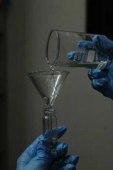
High concentration fluoride wastewater processing holds a [Ca²⁺]/[F⁻] molar ratio of 0.55 and a hydraulic retention time of at least 5 hours to reach 99% crystallization efficiency (per 2024 PMC study). Lab-scale rigs achieve that at 5-hour HRTs; full-scale deployment typically needs 8 to 12 hours. The allowance covers influent concentration swings and hydraulic turbulence in large 100 m³/h systems. Precise control is handled through PLC-controlled chemical dosing for pH adjustment and Ca²⁺/F⁻ ratio optimization, which prevents calcium overdosing and the calcium carbonate scaling that follows it.
Temperature acts as the main kinetic driver. Fluoride removal efficiency can drop by roughly 15% for every 10°C decrease below the optimal 40°C threshold. Industrial plants therefore use heat integration, often recovering latent heat from the evaporation stage to hold the crystallizer at 40°C–60°C. Upflow velocity in the fluidized bed must stay between 20–40 m/h for seed particles sized 0.5–1.0 mm. Too low and the bed collapses and clogs; too high and seed particles carry out with the effluent, halting crystallization.
| Design Parameter | Lab-Scale Optimal | Industrial Scale-Up Spec |
|---|---|---|
| Hydraulic Retention Time (HRT) | 5 Hours | 8 – 12 Hours |
| pH Level | 6.0 | 6.5 – 7.5 (to prevent corrosion) |
| [Ca²⁺]/[F⁻] Molar Ratio | 0.55 | 0.60 – 0.70 |
| Upflow Velocity | 30 m/h | 20 – 40 m/h (Variable Speed) |
| Seed Bed Height | 50 cm | 150 – 300 cm |
| Removal Efficiency | 99.5% | 98.0% – 99.2% |
Troubleshooting industrial systems starts with seed bed health. "Seed bed drift" occurs when average particle size grows too large, cutting the surface area available for new crystallization. Engineers should run a regular blowdown and make-up cycle, harvesting large crystals and introducing smaller seeds. Monitor pH drift as well: above 8.5 in carbonate-rich wastewater, calcium carbonate co-precipitates, lowering recovered CaF₂ purity and raising chemical consumption.
Calcium Fluoride Recovery from Wastewater: Byproduct Value and Purity Control
Calcium fluoride recovery from wastewater turns the treatment plant into a modest revenue source, because granular product from crystallization runs 95-98% pure CaF₂ and sells to steel mills as a fluxing agent. Market value runs $50 to $150 per ton in metallurgical and glass applications. Wikipedia's fluorite reference frames the grade ladder: "Metallurgical grade fluorite (60–85% CaF2)" serves steel flux duty, while acid grade demands "97% or more CaF2" for hydrogen fluoride production. Recovered crystals from a well-run crystallizer sit comfortably in metallurgical territory.
Purity control decides whether the byproduct sells or gets landfilled. Co-precipitation of silica or carbonates contaminates the crystal mass, so pre-treatment and pH discipline come first. Final dewatering must bring moisture below 20% for the product to be commercially viable for transport. A semiconductor plant producing 50 tons of fluoride waste per year can offset 10-15% of annual OPEX through recovery value alone.
Crystallization vs Electrocoagulation Fluoride: Decision Matrix for Buyers
Crystallization vs electrocoagulation fluoride comparisons come down to concentration, flow, and byproduct management. Evaporation crystallization systems carry a high initial CAPEX — typically $800,000 to $1.2 million for 100 m³/h capacity — but deliver superior efficiency on streams exceeding 500 mg/L F⁻. For plants with lower fluoride concentrations (10–50 mg/L), resin adsorption as an alternative for low-concentration fluoride streams offers lower entry cost, though resin replacement and regeneration chemicals lift long-term OPEX. Crystallization remains the only viable choice where zero-liquid discharge or resource recovery is the stated objective.
Set against electrocoagulation for small-footprint fluoride treatment, the choice often comes down to sludge. Electrocoagulation suits smaller flows and needs less chemical handling, but it produces a mixed hydroxide sludge that is difficult to recycle. Crystallization produces a granular solid at 95-98% CaF₂ purity that steel mills accept as flux, converting a cost center into a revenue generator. The decision framework should prioritize the fluoride concentration-versus-volume ratio: above 500 mg/L F⁻ and above 20 m³/h, crystallization wins on 10-year total cost of ownership through eliminated sludge disposal fees.
| Technology | Efficiency | CAPEX | OPEX ($/m³) | Byproduct |
|---|---|---|---|---|
| Evap. Crystallization | >99% | High | $0.80 – $1.50 | Reusable CaF₂ |
| Electrocoagulation | 90-95% | Medium | $0.30 – $0.60 | Hazardous Sludge |
| Resin Adsorption | >98% | Medium | $0.50 – $1.20 | Regenerant Brine |
| Chemical Precipitation | 80-90% | Low | $0.40 – $0.90 | Bulky Sludge |
High-volume, low-concentration streams justify a hybrid approach instead. Chemical precipitation handles the bulk load first, then crystallization-based ZLD treats the concentrated reject. That split keeps each stage inside its economic sweet spot and still delivers a dewatered byproduct rather than sludge.
Zero Liquid Discharge Fluoride Treatment: When It Justifies the CAPEX
Zero liquid discharge fluoride treatment becomes mandatory strategy wherever regulators or water scarcity close the discharge valve — China's ZLD mandates are the clearest example, and reuse-driven electronics plants follow the same logic. The economics work when three revenue lines stack: eliminated sludge disposal, CaF₂ crystal sales, and water reuse credits ($40k–$60k per year in the model below). Operators running ZLD also decouple production growth from effluent permit ceilings. For a worked example, our Wafer Fab Wastewater Case Study: 99.5% Fluoride & Silica Rem documents a compact ZLD system built around exactly this crystallization route.
Equipment Sizing and System Design: From Lab to Full-Scale Deployment
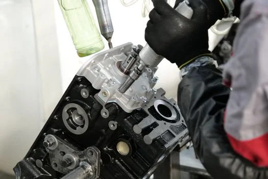
Reactor volume follows the formula V = (Q × HRT) / 24, so a 100 m³/h flow at an 8-hour industrial HRT needs a minimum 33.3 m³ effective reaction zone. Sizing must also absorb the internal circulation ratio. Many systems run 5:1 or 10:1 recirculation to keep the seed bed fluidized, which means internal pumps handle far more than nominal influent flow — with direct consequences for pipe sizing, pump head, and energy specs.
Wastewater chemistry dictates equipment selection. Forced circulation (FC) evaporators beat falling film designs on fluoride duty, because high solids content and CaF₂ scaling potential foul thin-film surfaces quickly. The crystallizer itself should be a fluidized bed reactor (FBR) or draft tube baffle (DTB) design for uniform crystal size distribution. Final separation belongs to high-efficiency CaF₂ crystal separation and dewatering with a recessed plate filter press, which drops crystal moisture below 20% for commercial transport.
Integration demands a robust pre-treatment stage. Suspended solids must fall below <10 mg/L before the crystallization reactor, or "amorphous fines" form and degrade crystal purity; a Dissolved Air Flotation (DAF) System is the usual guard stage for streams carrying FOG or fine TSS. Post-treatment typically adds a small polishing step — a sand filter or low-pressure membrane — to catch escaping micro-crystals. Automation is non-negotiable: a centralized PLC should manage high-accuracy dosing of calcium sources from real-time fluoride sensors, holding the molar ratio inside the 0.55–0.65 window even during process upsets.
Cost Analysis and ROI: Justifying the Investment to Stakeholders
Return on investment for industrial-scale evaporation crystallization is driven primarily by recovery of high-purity CaF₂ crystals, worth $50 to $150 per ton to metallurgical and glass buyers. Combined with avoidance of regulatory penalties — which can reach hundreds of thousands of dollars per incident — the business case clears easily in strictly regulated jurisdictions. A typical CAPEX split for a 100 m³/h system: 60% core equipment (evaporator, FBR, filter press), 20% installation and piping, 20% engineering and automation.
OPEX is dominated by evaporation energy, at $0.80 to $1.50 per cubic meter of treated water. Mechanical Vapor Recompression (MVR) cuts that energy consumption by up to 60% against traditional multi-effect evaporators. In a 2025 HydropureWater field study of a Singapore-based electronics manufacturer, a $1.1 million crystallization system paid back in 3.8 years, primarily by eliminating $280,000 in annual sludge disposal costs.
| Cost Category | Annual Expenditure (Estimated) | Savings/Revenue Drivers |
|---|---|---|
| Energy (MVR-based) | $80,000 – $120,000 | Elimination of Sludge Disposal ($200k+) |
| Chemicals (CaCl₂, NaOH) | $15,000 – $25,000 | CaF₂ Crystal Sales ($5k – $15k) |
| Maintenance & Labor | $30,000 – $50,000 | Water Reuse Credits ($40k – $60k) |
| Total Annual OPEX | $125,000 – $195,000 | Regulatory Risk Mitigation (Priceless) |
To maximize ROI, prioritize modular, skid-mounted systems that cut on-site installation time and labor. Selecting a vendor with ISO 14001 certification helps the equipment meet international environmental management standards, often a prerequisite for green financing or sustainability grants. Buyers weighing fluoride evaporation crystallization design options should request a site-specific budget through our industrial fluoride treatment quotation page, attaching influent fluoride data and target discharge limits for a sized proposal.
Frequently Asked Questions
What is the maximum fluoride concentration that evaporation crystallization can handle?
Evaporation crystallization handles streams from 500 mg/L to over 5,000 mg/L, and it is most efficient at the high end of that band. Unlike membrane or resin systems, it treats concentration as fuel rather than a fouling risk. Below 50 mg/L, it is normally used as a second-stage concentrator after primary treatment.
Can the recovered calcium fluoride (CaF₂) really be sold?
Yes, if purity exceeds 95%. Metallurgical industries use CaF₂ (fluorspar) as a flux to lower the melting point of raw materials. Marketability requires tight control against silica or carbonate co-precipitation and final dewatering to <20% moisture. Wikipedia's fluorite reference lists metallurgical grade at 60–85% CaF₂, so a 95-98% crystal product clears that bar comfortably.
How does this process handle other contaminants like arsenic or heavy metals?
Crystallization is highly selective for fluoride when pH and molar ratios are optimized. Heavy metals may co-precipitate as hydroxides, contaminating the CaF₂ crystals and cutting their value. In such cases, a pre-treatment precipitation step removes the metals before wastewater enters the fluoride crystallizer.
What is the typical lifespan of a fluoride crystallization reactor?
With proper material selection — Duplex stainless steel or rubber-lined carbon steel against fluoride corrosion — these systems run 15 to 20 years. The primary wear items are pump impellers and pH probes, which need periodic calibration and replacement. Budget those consumables into the maintenance line from year one.
Is zero liquid discharge fluoride treatment worth the extra CAPEX?
Yes, where discharge permits are closing, water reuse has real value, or regulators mandate it. Stacked savings — eliminated sludge disposal, CaF₂ sales, and water reuse credits — typically offset the premium within the 3.8-year payback observed in the 2025 Singapore field study. Hybrid precipitation-plus-crystallization designs keep the entry cost lower for mixed streams.
What upflow velocity should a fluidized bed fluoride crystallizer run at?
Hold upflow velocity between 20 and 40 m/h for seed particles sized 0.5–1.0 mm, with variable-speed drives to trim it. Below that band the bed collapses and clogs; above it, seed particles carry out with the effluent. Seed bed height of 150–300 cm at industrial scale gives the buffer for stable operation.