Silicon wafer wastewater treatment for 2026 pairs DAF, MBR, and RO into hybrid trains reaching COD ≤50 mg/L, TSS ≤10 mg/L, and 90% recovery; a 100 m³/h plant costs $5M–$15M with OPEX of $0.80–$2.50/m³. This semiconductor fab wastewater treatment capex breakdown maps the tiers.
Why Silicon Wafer Wastewater Treatment is a $15B Problem for Semiconductor Fabs
Silicon wafer wastewater treatment became a top-line cost item as 5nm nodes push ultrapure water demand to 5–10x legacy levels and mid-size fabs generate 500–2,000 m³/day of effluent. Modern plants recycle 70–90% of that water versus 30–50% in 2020, using hybrid DAF-RO-MBR trains with AOP for refractory organics.
Semiconductor fabrication at 5nm nodes needs 5 to 10 times more ultrapure water (UPW) per wafer than legacy 28nm processes, pushing wastewater volumes to 500–2,000 m³/day for mid-sized facilities. According to UltraFacility data, the shift toward advanced nodes introduces complex contaminants into the waste stream — cobalt, ruthenium, and molybdenum alongside conventional copper and fluoride. These materials arrive from CMP and advanced interconnect stages, creating a high-strength effluent beyond traditional municipal systems.
Regulatory risk has crossed a threshold as agencies tighten limits on per- and polyfluoroalkyl substances (PFAS) and toxic organics. In 2023, TSMC's Arizona fab faced approximately $1.2M in fines and remediation costs related to PFAS exceedances, underscoring the need for advanced Zero Liquid Discharge (ZLD) or Minimal Liquid Discharge (MLD) architectures. Compliance with EPA 40 CFR Part 469 and SEMI S23 is now a licensing prerequisite, not an option. Both mandate stringent COD and TSS controls, often below 50 mg/L and 10 mg/L respectively.
Water scarcity in Taiwan, Arizona, and Singapore forced the recycling shift. Modern fabs recycle 70–90% of their wastewater, up from the 30–50% rates common in 2020, driven by raw water cost and discharge fees. For a 5nm+ fab, skipping high-recovery high-recovery RO systems for UPW recycling in fabs risks millions in lost productivity during drought-induced rationing.
Ultrapure water quality anchors the economics. Semiconductor-grade UPW holds resistivity above 18.18 MΩ·cm, TOC below 1 μg/L, and silica below 50 ng/L (Wikipedia, Ultrapure Water). Advanced fabs consume several million gallons per day, and reclaimed feed carries urea-like organics that resist ion exchange and RO — one reason UV-AOP keeps appearing in sub-7nm water loops.
Silicon Wafer Wastewater Treatment Technologies: Side-by-Side Comparison
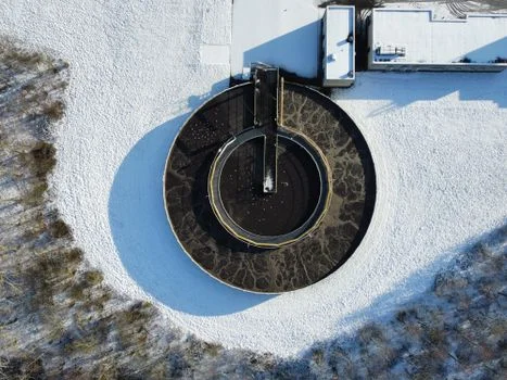
A side-by-side evaluation shows DAF serving as the primary solids stage while MBR and RO carry the low COD and TDS duties needed for recycling. Selecting the mix means balancing removal efficiency against energy consumption and footprint. CMP wastewater carries high concentrations of sub-micron silica or alumina particles that require specialized DAF systems for silicon wafer grinding wastewater to prevent downstream membrane scaling.
| Technology | Removal Efficiency (COD/TSS/Metals) | Footprint (m²/100 m³/h) | Energy Use (kWh/m³) | CAPEX ($/m³/h) | OPEX ($/m³) | Limitations |
|---|---|---|---|---|---|---|
| DAF (Dissolved Air Flotation) | 50-60% COD / 70-85% TSS / 40% Metals | 80–120 | 0.2–0.4 | $200–$400 | $0.10–$0.25 | Low removal of dissolved organics; requires high chemical dosing. |
| MBR (Membrane Bioreactor) | 85-92% COD / 95-99% TSS / 60% Metals | 150–250 | 0.8–1.2 | $800–$1,200 | $0.40–$0.70 | Susceptible to fouling from CMP slurries; requires robust pre-treatment. |
| RO (Reverse Osmosis) | 90-95% COD / 99% TSS / 98% Salts | 200–300 | 1.2–2.5 | $1,000–$1,500 | $0.60–$1.20 | High salt concentration in concentrate; membrane life sensitive to pH. |
| AOP (UV/H₂O₂) | 92-97% COD / 0% TSS / 0% Metals | 40–60 | 2.5–5.0 | $600–$1,000 | $1.00–$2.50 | High energy cost; does not remove solids or salts. |
The data points to an MBR Membrane Bioreactor Wastewater Treatment System as the most cost-effective organic-removal core, but only when DAF handles solids first. Patent CN104150624A quantifies the stakes: without 70%+ TSS removal in the DAF stage, downstream MBR and RO membranes lose 60% of flux within the first 48 hours. Advanced oxidation (AOP) remains the only viable destruction route for refractory organics like PFAS, though its OPEX confines it to high-concentration streams.
Hybrid System Design: Combining DAF, RO, and MBR for Zero-Fouling Performance
Hybrid DAF-MBR-RO process flow achieves TSS below 1 mg/L and up to 90% water recovery in modern fabs. Stage one floats out the bulk of CMP slurries with DAF operating at 4–6 bar. The biological MBR stage follows at 0.1–0.3 bar, degrading organic solvents and nitrogenous compounds. High-pressure RO at 15–25 bar then removes residual salts and trace heavy metals, producing water fit for re-entry into the UPW makeup loop.
Zero-Fouling MBR System for Semiconductor Fab Duty
Membrane fouling from photoresist strippers and etching surfactants is the problem a zero-fouling MBR system for semiconductor fab duty exists to solve. Real-world data from Veolia's Soitec plant in Singapore shows zero-fouling PVDF membranes for MBR systems cutting chemical cleaning from once per week to once per quarter. Their permanent hydrophilic coating resists adsorption of hydrophobic organics. That single modification trims total system OPEX by roughly $0.30/m³ through longer membrane life and lower chemical consumption.
For 5nm nodes and below, an AOP loop often slots between MBR and RO. The UV/H₂O₂ process targets refractory organics that biology cannot break down. Total energy for the integrated hybrid system typically runs 1.2 to 2.0 kWh/m³, according to IDE Technologies. Following 2027 engineering specs for silicon wafer wastewater equipment, engineers can meet discharge limits while hedging municipal water costs, which can reach 15% of a fab's operational budget.
Semiconductor Fab Wastewater Treatment CAPEX Breakdown: 100 m³/h Plant
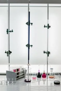
Semiconductor fab wastewater treatment capex breakdown numbers for a 100 m³/h plant run $5 million to $15 million, set by contaminant complexity and the required recycling degree. RO and MBR together account for nearly 50% of the equipment budget. Automation and SCADA integration add $200K–$300K for real-time effluent monitoring and permit compliance. The table below details a standard 100 m³/h fab wastewater plant budget.
| Cost Category | CAPEX Estimate ($) | Annual OPEX ($) | Technical Notes |
|---|---|---|---|
| DAF System (Pre-treatment) | $200,000 – $400,000 | $45,000 – $60,000 | Includes chemical dosing skids and sludge thickening. |
| MBR System (Biological) | $800,000 – $1,200,000 | $120,000 – $180,000 | Based on zero-fouling PVDF membranes for MBR systems. |
| RO System (Polishing/Recycling) | $1,000,000 – $1,500,000 | $180,000 – $300,000 | Includes antiscalant dosing and CIP stations. |
| AOP System (PFAS/VOC Removal) | $600,000 – $1,000,000 | $250,000 – $400,000 | High energy and reagent (H₂O₂) requirements. |
| Pumps, Piping & Installation | $1,500,000 – $3,000,000 | $20,000 – $40,000 | Requires SS316L for corrosive etching waste. |
| Automation & Control (SCADA) | $200,000 – $300,000 | $15,000 – $25,000 | Real-time TOC and heavy metal sensors. |
| Total Estimated Cost | $5,000,000 – $15,000,000 | $0.80 – $2.50 / m³ | ROI achieved in 3–5 years via UPW cost savings. |
OPEX is dominated by energy and membrane replacement. Energy averages $0.50–$1.20/m³ and membrane replacement $0.15–$0.40/m³. Recycling into the UPW loop pays it back: raw water typically costs $0.50–$1.50/m³ in industrial zones, and a 100 m³/h system at 85% recovery can save more than $1 million per year in water procurement alone. That math drives the 3-to-5-year payback for high-efficiency ZLD systems.
Saw-related duty rides the same economics. Search teams also arrive looking for reverse osmosis water for wafer saw rinse recycling, which uses the same salt-rejection logic and the same cost tiers described here.
Compliance Standards: SEMI S23, EPA 40 CFR Part 469, and Local Limits
Effluent compliance for semiconductor manufacturing is governed by EPA 40 CFR Part 469 and SEMI S23, which mandate strict limits on toxic organics, heavy metals, and PFAS. SEMI S23 provides the industry benchmark for energy and water efficiency, recommending COD ≤50 mg/L and TSS ≤10 mg/L before discharge. Heavy metal limits keep tightening, with copper often restricted to ≤0.5 mg/L and nickel to ≤1.0 mg/L to protect downstream biological plants. These limits sit well below PV wastewater treatment specs for solar cell fabs, reflecting the higher complexity of IC manufacturing.
Local rules often exceed federal standards in semiconductor-dense regions. Taiwan's Environmental Protection Administration sets COD limits as low as 60 mg/L for industrial parks, and Arizona has proposed PFAS limits as low as 14 ppt for certain aquifers. Singapore's Public Utilities Board enforces TDS ≤1,000 mg/L for industrial discharge to protect NEWater recycling. Meeting that spread requires a multi-barrier approach — AOP for PFAS and VOCs, RO for TDS, MBR for COD and TSS — plus continuous pH (6.0–9.0) and TOC monitoring to avoid shut-off and penalties.
Federal PFAS pressure sharpened in April 2024. EPA finalized the first national drinking-water standard for PFAS, setting MCLs of 4.0 ppt each for PFOA and PFOS, plus limits for PFNA, PFHxS, and HFPO-DA and a Hazard Index for mixtures (US EPA, 2024).
How to Select the Right Silicon Wafer Wastewater Treatment System
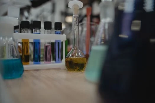
Selection starts with influent chemistry, specifically CMP slurry and etching solvent concentrations, weighed against internal reuse targets. First, quantify total wastewater volume and segment it by contaminant type. Grinding and CMP streams, high in TSS, need robust DAF pretreatment. Etching and cleaning waste, rich in acids and organics, needs neutralization plus biological treatment via MBR.
Second, assess UPW recycling needs: 70–90% recycling is standard for 5nm+ fabs and mandates RO plus potentially AOP, while legacy 28nm fabs at 30–50% recycling may suffice with a simpler DAF-MBR setup. Third, weigh CAPEX and OPEX constraints — AOP delivers the highest PFAS removal but its energy use is prohibitive unless local limits demand it. Finally, pilot test zero-fouling PVDF membranes for MBR systems with actual fab effluent to verify flux and cleaning intervals. That empirical step is the only way to verify the 99.9% uptime a modern fab expects, and the Wafer Fab Wastewater Treatment Equipment: 2026 Engineering Specs page adds a cost-optimized selection guide for the shortlist.
Startup Sequence and Monitoring Cadence
Bring the train up in order — hydraulics on clean water, DAF chemistry balanced, biology seeded and acclimated, then RO brought online once MBR permeate clears. Only then close the recycle loop to the UPW makeup. Acceptance should ride on consecutive shifts at design flow, not a single good sample.
Run a fixed monitoring rhythm afterward. Track pH, flow, and TOC continuously; check DAF skimmer performance and membrane pressure daily; sample the permit parameters on the regulatory calendar. Keep one operator log across all stages — cleaning events, dosing changes, and CMP line washdowns recorded there explain most excursion investigations months later. Review it monthly with the vendor service engineer before small drifts become permit events.
Next Step: Turn These Specs Into a Budget
Plant engineers, EPC contractors, and procurement teams sizing a fab effluent plant can move straight from this framework to numbers. Send your flow rate, influent profile, and discharge limits for a quote — enough data to place the project inside the $5M–$15M tiers with a stage-by-stage mass balance.
Frequently Asked Questions
How do you treat CMP wastewater for recycling?
CMP wastewater is treated with DAF to remove abrasive silica and alumina particles, then MBR for organic removal. Recycling the water into UPW requires a final RO stage to reach TDS below 50 ppm. Most fabs also hold DAF recovery above 70% TSS removal, because downstream membranes lose flux quickly below that threshold.
What are the EPA 40 CFR Part 469 limits for semiconductors?
40 CFR Part 469 sets categorical limits for the semiconductor subcategory centered on total toxic organics (TTO), fluoride, and pH. No federal PFAS effluent limit exists yet, though EPA's April 2024 drinking-water rule set 4.0 ppt MCLs for PFOA and PFOS, tightening state permit expectations.
How can MBR membrane fouling be prevented in semiconductor fabs?
Fouling is prevented with asymmetric PVDF membranes carrying permanent hydrophilic coatings, operated at a cross-flow velocity that stops cake layer formation. Pretreatment with DAF to remove 80%+ of suspended solids protects the MBR stage upstream. Quarterly-rather-than-weekly cleaning cycles, as demonstrated at Veolia's Soitec plant in Singapore, are the realistic target for a well-designed train.
What does silicon wafer grinding wastewater treatment cost with full ZLD?
Silicon wafer grinding wastewater treatment cost with full ZLD typically lands between $10 million and $15 million for a 100 m³/h fab. The scope includes DAF, MBR, RO, and an evaporator or crystallizer for final brine concentration. Grinding-dominated streams trend toward the lower half of that band because DAF carries most of the solids load.
Which method handles PFAS removal in semiconductor wastewater 2026 and beyond?
Advanced Oxidation Processes lead PFAS removal in semiconductor wastewater 2026 planning. High-intensity UV light combined with hydrogen peroxide generates hydroxyl radicals that break the carbon-fluorine bonds in PFAS molecules, mineralizing them into fluoride ions and CO₂. EPA's April 2024 drinking-water rule at 4.0 ppt for PFOA and PFOS keeps pushing fabs toward AOP loops despite the energy cost.