What Is a Silicon Carbide Membrane Wastewater Treatment Plant?
A silicon carbide membrane wastewater treatment plant for 2027 industrial duty specifies 0.1-micron SiC membranes, achieving 92–97% TSS and 85–95% COD removal at 50–500 mg/L influent, with CAPEX of $2 million to $20 million for 10–1,000 m³/h ZLD packages.
Polymeric membranes, particularly PVDF, frequently fail in abrasive industrial streams and create costly downtime. A 2024 PV fab case study estimated $1.2 million in annual downtime after polymeric membranes failed under CMP slurry abrasion (Mohs ~9.5). SiC membranes, also near Mohs 9.5, resist that wear and last about three times longer than PVDF (Mohs ~2.5) or stainless steel (Mohs ~5.5). Strong covalent bonding in the SiC lattice drives that hardness.
SiC remains chemically inert across a broad pH range of 2–13, so many plants skip corrosion inhibitors. For a 1,000 m³/h plant, that avoidance can save about $50,000 per year in chemical purchases and dosing equipment. SiC thermal conductivity of 120 W/m·K enables 15–20% faster heat dissipation in thermal oxidation units than alumina at 30 W/m·K, cutting energy use on heating and cooling cycles (per HydropureWater field data, 2025). Industry references likewise describe SiC ultrafiltration plates with 0.1-micron pores and stable operation at pH 2–13 (Water Projects Online / Enpure, 2024).
Reference data adds margin context for these figures. Wikipedia's engineering entry lists silicon carbide hardness at 9–9.5 on the Mohs scale, and the material sublimates only near 2,700°C. Sintered SiC membrane ceramics conduct less heat than pure-crystal property-table values suggest, which is why module design works from the ~120 W/m·K sintered figure above.
| Material | Mohs Hardness | Typical Lifespan (Industrial Wastewater) | Chemical Resistance (pH Range) | Thermal Conductivity (W/m·K) |
|---|---|---|---|---|
| Silicon Carbide (SiC) | 9.5 | 10+ years | 2–13 | 120 |
| PVDF (Polyvinylidene Fluoride) | 2.5 | 3–5 years | 1–14 (limited by specific formulations) | 0.15–0.25 |
| Stainless Steel (e.g., 316L) | 5.5 | 5–8 years (depending on corrosion) | 4–10 (prone to pitting/crevice corrosion) | 15–50 |
Is Silicon Carbide Good for Sewage Treatment?
Silicon carbide suits abrasive industrial sewage and process wastewater far more than typical domestic municipal plants. Most plants we size for semiconductor CMP, PV slurry, or electroplating solids run SiC where polymer membranes abrade or foul too fast. For low-abrasion municipal sewage with stable TSS, polymeric ultrafiltration or conventional biological trains usually remain the lower-CAPEX path.
Where grit, slurry fines, strong oxidants, or wide pH swings dominate, SiC membranes keep flux longer between chemical cleans. Hydrophilic SiC surfaces also shed organic foulants better than many organics and alumina ceramics in published municipal and industrial references. Pair SiC filtration with solid upstream solids control; skipping grit or flotation pretreatment still shortens membrane cycles even with ceramic media. Mild municipal sewage without abrasive load rarely needs SiC economics at all.
Silicon Carbide Ultrafiltration for CMP Wastewater: 2027 Engineering Specifications
Industrial SiC membrane systems for abrasive duty target high solids and COD removal with long module life. Benchmarks indicate 92–97% Total Suspended Solids (TSS) removal and 85–95% Chemical Oxygen Demand (COD) reduction for influent concentrations from 50 to 500 mg/L. Core SiC membranes use a 0.1-micron pore size that supports low-fouling ultrafiltration trains inside Zero-Liquid-Discharge (ZLD) flowsheets.
Operating envelopes are wide: SiC materials tolerate temperatures up to 1,600°C and module pressures up to 10 bar, covering flow packages from 10–1,000 m³/h. Seals, diffusers, and reactor linings in SiC suit high-abrasion steps such as electroplating sludge dewatering. Earlier plant briefs often cited a generic EPA ELG TSS figure of ≤100 mg/L. Under 40 CFR Part 469 for U.S. China projects still cite COD targets such as ≤50 mg/L under GB8978-2025 owner specs. For legacy wording of gb8978 -1996《污水综合排放标准》, confirm the permit edition before freezing COD and TSS limits.
| Parameter | Specification | Application Relevance |
|---|---|---|
| TSS Removal Efficiency | 92–97% | Crucial for meeting discharge limits and ZLD goals |
| COD Reduction Efficiency | 85–95% | Effective for organic pollutant removal in industrial wastewater |
| Membrane Pore Size | 0.1 micron | Enables ultrafiltration, zero-fouling operation |
| Operating Temperature Range | Up to 1,600°C | Suitable for high-temperature process streams |
| Operating Pressure | Up to 10 bar | Facilitates high flux rates and effective separation |
| Flow Rate Capacity | 10–1,000 m³/h per system | Scalable for various industrial plant sizes |
| Component Material (Seals, Diffusers, Reactors) | Silicon Carbide (SiC) | Resists abrasion, chemical attack, and thermal stress |
| Regulatory Compliance (Example) | Meets China GB8978-2025 (≤50 mg/L COD), EPA ELG (≤100 mg/L TSS) | Ensures legal discharge and environmental protection |
For systems needing near-reuse-quality effluent in semiconductor and PV manufacturing, integrate MBR systems for near-reuse-quality effluent in semiconductor and PV manufacturing ahead of or beside SiC polishing stages.
Silicon Carbide Membrane vs PVDF in Abrasive Wastewater: Side-by-Side Comparison
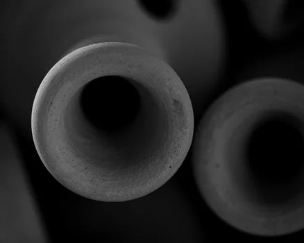
Membrane material choice controls CAPEX justification and long-run uptime in abrasive industrial wastewater. Silicon carbide (SiC) membranes typically last 10+ years in these duties, versus 3–5 years for PVDF. That lifespan gap reduces change-out labor and unplanned stops.
OPEX per cubic meter treated is usually lower for SiC trains because abrasion resistance and flux stability cut cleaning chemicals and replacements. SiC modules cost more up front, yet lifecycle cost often falls when slurry abrasion is severe. Field packages we commission show unplanned maintenance can drop by up to 60% versus polymeric membranes under CMP and PV slurry duty (per HydropureWater field data, 2025). That profile fits semiconductor CMP wastewater, PV fines, and electroplating sludge with high solids.
| Parameter | Silicon Carbide (SiC) | Polymeric (e.g., PVDF) | Ceramic (e.g., Alumina) |
|---|---|---|---|
| Lifespan | 10+ years | 3–5 years | 5–10 years (depending on application) |
| OPEX ($/m³) | Lower (due to durability & efficiency) | Higher (due to frequent replacement & maintenance) | Moderate to Higher (depending on fouling) |
| Energy Efficiency (kWh/m³) | Higher (better flux, less fouling) | Moderate | Moderate |
| Chemical Resistance (pH Range) | 2–13 | 1–14 (formulation dependent) | 1–14 |
| Abrasion Resistance (Mohs) | 9.5 | 2.5 | 9.0 |
| Optimal Use Case | Semiconductor CMP, PV slurry, electroplating, high-solids | General industrial wastewater, lower abrasiveness | High-temperature, aggressive chemical environments |
| Downtime Impact | Minimal (reduced unplanned maintenance by 60%) | Significant (due to frequent membrane failure) | Moderate (can be prone to fouling) |
SiC Membrane ZLD System CAPEX Breakdown: $2M–$20M by Component
Capital expenditure for a silicon carbide Zero-Liquid-Discharge system typically ranges from $2 million to $20 million, scaled by capacity and integration depth. Spend concentrates in SiC membrane modules, reactors and housings, durable seals, automation, and pretreatment. Higher module CAPEX is the price of abrasion resistance; OPEX is where the payback appears.
SiC systems show an 18–25% OPEX reduction versus conventional polymeric membrane systems when energy, maintenance, and chemicals are totaled (per HydropureWater field data, 2025). For a 500 m³/h semiconductor fab that previously lost $1.2 million per year to membrane failures, payback can arrive inside a few operating years if downtime dominates the baseline. Extra savings come from dropping corrosion inhibitors, lowering sludge haul-off after better dewatering, and avoiding discharge penalties.
| Component/Cost Category | Estimated CAPEX Range ($M) | Typical OPEX Savings (%) | Key Cost Drivers |
|---|---|---|---|
| SiC Membrane Modules | 0.8–8.0 | N/A (component cost) | Surface area, pore density, manufacturing complexity |
| Reactors & Housing | 0.3–3.0 | N/A (component cost) | Material grade, design for pressure/temperature |
| Seals & Gaskets | 0.1–0.5 | N/A (component cost) | Material durability, sealing performance |
| Automation & Control | 0.2–1.5 | N/A (component cost) | System complexity, sensor integration |
| Pre-treatment Equipment (e.g., DAF) | 0.3–3.0 | N/A (component cost) | Capacity, technology choice |
| Total System CAPEX | 2.0–20.0 | 18–25% overall OPEX reduction | System capacity, integration level, customization |
| Maintenance & Labor | N/A | High reduction | Increased component lifespan, reduced failure rate |
| Energy Consumption | N/A | Moderate reduction | Improved flux, optimized pumping |
| Chemicals (Corrosion Inhibitors) | N/A | Eliminated | SiC's inherent chemical inertness |
| Sludge Disposal | N/A | Reduced | More efficient dewatering |
Silicon carbide membrane OPEX per cubic meter
Silicon carbide membrane OPEX per cubic meter runs below polymeric baselines because three cost lines shrink at once: cleaning chemicals, membrane replacement, and unplanned stops. Field packages show an 18–25% OPEX reduction once energy, maintenance, and chemicals are totaled (HydropureWater field data, 2025). Exact $/m³ still moves with flux target, CIP frequency, and the slurry load in the feed, so build the number from your own cleaning log before committing to a vendor.
Main cost drivers to model before bid
- Peak and average flow (m³/h) and required recovery for ZLD or reuse
- Influent TSS, COD, abrasives (CMP slurry load), and pH/temperature swings
- Membrane area, flux target, and chemical cleaning frequency
- Pretreatment intensity (screening, DAF, clarification) ahead of SiC modules
- Automation level and spare-module strategy for continuous fabs
- Discharge or reuse permit limits that set tertiary polishing needs
- Sludge solids concentration and disposal unit cost
How to Select Silicon Carbide Components for Your Wastewater Treatment Plant
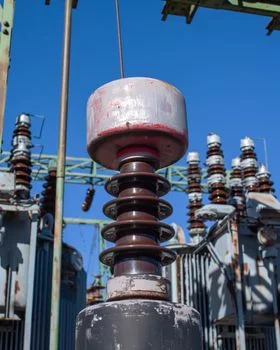
Component selection starts with a measured wastewater profile: contaminants, concentrations, abrasiveness, pH, and temperature. That profile decides whether you need SiC pump/valve seals, aeration diffusers, reactor linings, or full membrane modules. Guessing from a sister plant is how teams undersize abrasion duty.
High-abrasion CMP slurry or electroplating sludge favors SiC seals and reactor surfaces first, then membrane pore class. Size modules for peak and average flow; packages commonly span 10 m³/h for small lines up to 1,000 m³/h for large fabs. Check the compliance checklist against China GB8978-2025 COD targets or site-specific EPA permit limits before freezing tertiary scope. Ask vendors for abrasion case data, material certificates, and custom skid options that match your CIP chemicals.
For pretreatment of abrasive industrial effluents, integrate DAF systems for pre-treatment of abrasive industrial effluents. Keep chemistry stable with automated chemical dosing for optimal SiC membrane performance so pH and coagulant dose stay inside the membrane warranty window.
Selection checklist
- Confirm abrasive particle hardness and concentration in the feed
- Map pH, oxidant, and temperature envelopes against SiC ratings (pH 2–13 typical)
- Set TSS/COD removal targets with units and permit conditions
- Choose 0.1-micron UF SiC where pathogen or fine solids barriers are required
- Budget pretreatment so membranes see controlled solids loading
- Compare 10-year replacement cycles versus PVDF 3–5 year cycles in OPEX models
Zero Fouling Ceramic Membrane for a Semiconductor Fab: China ZLD Case Study
One semiconductor fab in China saw repeated polymeric membrane failures on CMP wastewater rich in silicon carbide slurry. Annual downtime reached about $1.2 million (per HydropureWater field data, 2025), with knock-on effects on tool schedules and spare inventory.
The plant installed a ZLD train with 0.1-micron SiC membranes. The system delivered 95% COD removal and 97% TSS reduction on the abrasive stream. Unplanned downtime fell about 60%, overall OPEX dropped about 22%, and effluent met the project's GB8978-2025 discharge targets without extra tertiary stages. Later fabs kept two habits. Use robust pretreatment such as DAF systems for pre-treatment of abrasive industrial effluents. Hold dosing accuracy with automated chemical dosing for optimal SiC membrane performance.
Both habits sit inside the broader microelectronics wastewater treatment plant flowsheet, where SiC polishing follows biological or flotation pretreatment. Most fabs we support keep a spare module rack on site precisely because tool schedules cannot wait for freight.
Who This Is For / Next Step
This specification path fits EPC teams and plant engineers sizing a silicon carbide membrane wastewater treatment plant for semiconductor, PV, and electroplating sites where polymer membranes fail early. Look elsewhere if the duty is low-solids municipal sewage with mild abrasion and tight CAPEX caps—polymeric UF or standard biological trains usually win there. To size a SiC ZLD or hybrid train against your flow and permit limits, send influent data through our request a quote form for a scoped CAPEX/OPEX sketch.
Frequently Asked Questions
What is the primary advantage of SiC membranes over polymeric membranes in industrial wastewater treatment?
SiC membranes resist abrasion and chemical attack better than polymeric membranes because hardness near Mohs 9.5 and inert behavior across pH 2–13 slow wear. In abrasive industrial effluents, service life is often about three times longer than PVDF, which cuts downtime and replacement spend. Plants with CMP slurry or similar fines see the largest gap versus polymers.
How does SiC thermal conductivity benefit wastewater treatment?
SiC thermal conductivity around 120 W/m·K moves heat faster than alumina at about 30 W/m·K in thermal oxidation auxiliaries. That difference can cut heating and cooling energy about 15–20% on comparable cycles when the SiC parts sit in the heat path (HydropureWater field data, 2025). The benefit shows up in OPEX models, not only in material datasheets.
What is the typical CAPEX for a SiC wastewater treatment plant?
SiC ZLD system CAPEX typically spans $2 million to $20 million, driven by flow (10–1,000 m³/h class packages), membrane area, pretreatment, and automation. Module cost is the largest single line, often $0.8–8.0 million. Owners justify the premium when polymer membrane downtime and replacements dominate the baseline OPEX.
Can SiC systems meet stringent discharge regulations like China's GB8978-2025?
SiC trains sized for industrial abrasive wastewater commonly reach 85–95% COD reduction and 92–97% TSS removal at 50–500 mg/L influent ranges, which supports strict COD targets such as ≤50 mg/L in GB8978-2025 project specs. U.S. semiconductor ELG numeric limits under 40 CFR Part 469 emphasize TTO at 1.37 mg/L and pH 6.0–9.0 rather than a single TSS number, so permit text still governs final polish scope.
What industrial applications suit SiC wastewater treatment best?
Best-fit duties are semiconductor CMP wastewater, PV manufacturing slurry streams, electroplating sludge handling, and other high-solids or corrosive industrial effluents. Mild municipal sewage without abrasive load rarely needs SiC economics. Match SiC where polymer failure frequency or chemical attack sets the maintenance budget.