The lime dosing system working principle centers on controlled calcium hydroxide (Ca(OH)₂) injection for pH control, softening, or heavy-metal precipitation. The train typically includes a lime silo with vibration to limit bridging and a slurry tank held at 8–15% by weight. Continuous agitation is mandatory because lime settles within 2 minutes without mixing, and the dosing pump needs large-bore valves for abrasive slurry. Pipeline velocity stays above 1.5 m/s, while a PID loop from an online analyzer regulates pH across ETP, STP, mining, and semiconductor duties.
Lime Dosing System Working Principle: From Silo to pH Probe
A lime dosing system stores powdered lime, converts it into an agitated 8–15% slurry, meters that slurry with a positive-displacement pump, and trims the dose through a PID loop reading an online pH probe. Every stage must tolerate abrasion and high alkalinity. The measurement chain, not the pump, sets the accuracy of the train.
In operation, the sequence runs storage, slaking or make-up, metering, and feedback correction. A screw feeder or gravimetric feeder draws powder from the silo into the slurry tank, where the agitator holds the charge in suspension. According to US EPA design data, slaking is the chemical process that makes quicklime reactive in water, and quicklime should never be applied dry because it reacts unevenly with water.
| Component | Engineering Specification | Material / Design Standard |
|---|---|---|
| Lime Silo | 5–50 m³ capacity; Radar level sensing | Carbon Steel with Epoxy Coating; <10 Hz Vibration |
| Screw Conveyor | 10–50 RPM; 0.5–5 m³/h capacity | 304/316 Stainless Steel; Shaftless design preferred |
| Slurry Tank | 8–15% concentration by weight | Pitched-blade impeller; 30–60 RPM Agitator |
| Dosing Pump | 0.1–50 L/h; High-viscosity capability | Diaphragm or Peristaltic; Hastelloy/316 SS valves |
| Static Mixer | 3–5 mixing elements; <0.5 bar pressure drop | PVC or Stainless Steel; 1–3 m/s velocity |
| pH Analyzer | Online probe; ±0.02 pH accuracy | Auto-cleaning (acid wash) every 24 hours |
To prevent the lime-settles-in-2-minutes failure mode, the agitator runs continuous duty, and pitched-blade impellers are preferred because they generate both axial and radial flow that lifts solids off the tank floor. The lime-based FGD scrubbers for SO₂ removal and gypsum recovery apply the same slurry discipline where absorber kinetics demand tight density control.
How to Design a Lime System for Post Treatment: Settling, Bridging, and Velocity
Engineers who ask how to design a lime system for post treatment usually fight three physical problems: fast settling, silo bridging, and pH overshoot. Each problem has a numeric design rule rather than a brand decision. The three rules below come from the same operating envelope.
Lime Settling Physics: Why Agitation Never Stops
Lime particles generally range from 1 to 50 μm in diameter. According to ASTM C110-20 test methods, which include a settling-rate procedure for hydrated lime, particles of this size settle at 0.1 to 0.5 mm/s in stagnant water. Because lime has a specific gravity of 2.24, it will not stay suspended without continuous energy input. Stopping the agitator even briefly starts a compacted bed that chokes the pump suction.
Lime Silo Bridging Troubleshooting: Hopper Angle and Vibration
In storage, the main failure mode is bridging or arching inside the silo. Lime powder has a cohesive strength of 2–5 kPa, so it can span the hopper outlet and stop flow entirely. Vibration is the usual fix, yet engineering data from Haibar Machinery shows frequencies above 10 Hz can compact the powder and worsen the bridge. Effective silo design uses low-frequency, high-amplitude vibration, a steep hopper angle above 60 degrees, and an outlet sized for mass flow.
Downstream of dosing, the solids that lime creates still need separation. The lamella clarifier working principle governs that settling step, and plate spacing must match the lime floc load your train generates.
Lime Slurry Concentration for Wastewater Treatment: Holding the 8–15% Band
The workable lime slurry concentration for wastewater treatment sits between 8 and 15% by weight, held by continuous agitation in the make-up tank. Below that band the pump moves mostly water and loses turndown, while above it undissolved lime accumulates and drives the overshoot behavior covered later in this article. The band is a mechanical limit, not a suggestion.
US EPA design data draw a related line: the concentration of a clarified lime solution is usually kept at or below 6 percent. Clarified solution suits low-dose duties, whereas agitated 8–15% slurry suits the metered trains described here.
Softening targets follow chemistry rather than habit. According to EPA design data, magnesium in most wastewaters is not precipitated until enough lime is added to raise the pH above 10.0. Phosphorus removal cited in the same document needed a pH of at least 9.85, reached at a lime dose of 150 mg/L.
For selection ranges and cost bands beyond this process focus, see the sibling guide Lime Dosing System Explained: Engineering Specs, Cost Data & Industrial Selection. Readers wanting stage-by-stage detail can open lime dosing process in water treatment explained as a companion walkthrough.
Dry vs. Wet Lime Dosing System Comparison: CAPEX, Accuracy, and Duty
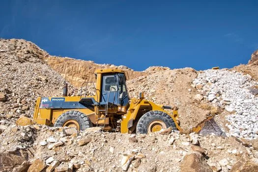
Wet dosing is the usual choice when accuracy matters. Premixing lime to about 10% lets the pump meter chemical more tightly than a screw feeder on dry powder, and that precision is critical in semiconductor and food plants with narrow pH windows. Dry dosing earns its place at high tonnage, where dust collection and screw wear cost less than slurry make-up.
| Criteria | Dry Dosing System | Wet Dosing System |
|---|---|---|
| Typical CAPEX | $20,000 – $50,000 | $30,000 – $80,000 |
| Lime Consumption | Best for >100 kg/day | Best for <50 kg/day or Variable Flow |
| Dosing Accuracy | ±5–10% | ±1–2% |
| Maintenance Needs | High (Dust, Screw wear) | Moderate (Pump valves, Agitator) |
| Primary Use Case | Mining, Heavy Industrial Neutralization | Municipal ETP, Food/Beverage, Semi-con |
When lime is paired with polymer, as in how PAM dosing systems complement lime for coagulation and flocculation, wet dosing supports synchronized chemical delivery and cleaner primary clarifier performance.
How Should Lime Metering and Lime Dosing Be Matched?
Lime metering sets the dry feed or slurry make-up rate. Lime dosing is the wet delivery into the process line under pH feedback, and abrasion rules out standard centrifugal pumps because impellers and seals fail quickly. Engineers therefore choose among three positive-displacement options.
- Diaphragm Pumps: Common for higher flows (5–50 L/h), with strong chemical resistance but recurring valve-seat wear.
- Peristaltic Pumps: Suited to lower flows and tight accuracy; slurry contacts only the hose, so there are no valves to clog.
- Progressive Cavity (PC) Pumps: Reserved for high-viscosity lime paste duties up to 50% solids.
| Pump Type | Max Solids | Maintenance Frequency | Typical Failure Mode |
|---|---|---|---|
| Diaphragm | 15% | 3–6 Months | Valve seat abrasion/clogging |
| Peristaltic | 25% | 12–24 Months | Hose fatigue/rupture |
| Progressive Cavity | 50% | 12 Months | Stator wear from dry run |
Diaphragm vs. Peristaltic Pump for Lime Slurry Duty
Between diaphragm and peristaltic pumps for lime slurry, diaphragm units handle higher flows of 5–50 L/h but need valve inspection every 3–6 months. Peristaltic hoses isolate the slurry completely, run 12–24 months between changes, and suit low-flow, high-accuracy duties. Progressive cavity pumps stay reserved for paste service up to 50% solids, provided they are never run dry.
pH Overshoot and PID Tuning in Lime Dosing
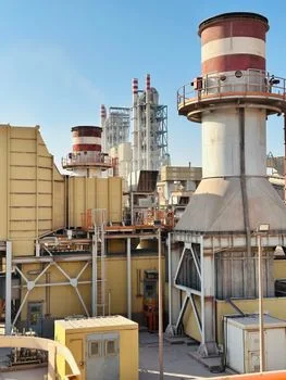
pH control with lime is difficult because the scale is logarithmic and Ca(OH)₂ dissolves slowly, so a standard PID loop must account for dead time between injection and probe response. EPA design data put the pH of a saturated lime solution near 12.4, which shows how far an unchecked dose can push a weakly buffered stream. That lag is a sizing input, not a tuning afterthought.
Process instability often appears as pH overshoot past the setpoint with slow recovery, and preparing slurry above 15% is a frequent cause. Excess lime stays as suspended solids and dissolves over several minutes. By the time the online probe reacts, the PLC-controlled lime dosing systems for precise pH adjustment have already injected too much slurry, producing the delayed spike documented in a Premix Technologies case study.
According to EPA 2024 benchmarks, these PID parameters form a baseline for many industrial wastewater streams:
- Proportional Band: 20–50%.
- Integral Time: 0.5–2.0 minutes.
- Derivative Action: 0–0.5 minutes.
Validate tuning with a step-change test: shift influent pH manually and time the recovery to setpoint, with stabilization inside 5 minutes as the usual target. Discharge limits often frame that target. US EPA secondary drinking water guidance sets a recommended pH range of 6.5 to 8.5, which many plants adopt as a neutralization endpoint.
Lime Dosing Troubleshooting: Symptom-to-Solution Checks
When a lime train fails, symptoms usually map to one physical or mechanical cause. Run the checks below before changing setpoints or pump curves.
Symptom: pH is not rising despite the pump running at full stroke
- Cause 1: Lime silo bridging. Solution: Check silo level; activate vibration pads.
- Cause 2: Pump valve failure. Solution: Inspect diaphragm pump valves for wear; replace if necessary.
- Cause 3: Slurry concentration too low. Solution: Recalibrate screw feeder to water ratio (target 10%).
Symptom: Frequent pipeline blockages
- Cause 1: Velocity below 1.5 m/s. Solution: Increase pump speed or reduce pipe diameter to boost velocity.
- Cause 2: Lack of flushing. Solution: Program the PLC to flush the lines with water for 5 minutes after every dosing cycle.
Symptom: pH readings are drifting or erratic
- Cause: Probe fouling. Lime scale (calcium carbonate) builds up on the glass bulb. Solution: Implement an automated 5% HCl acid wash every 24 hours.
Lime handling also carries an occupational limit. According to the NIOSH Pocket Guide, calcium oxide carries a recommended exposure limit of 2 mg/m3 as a TWA, with an IDLH value of 25 mg/m3. Dust collection at the silo and sealed powder transfer are therefore baseline requirements for any dosing building.
After pH correction and heavy-metal precipitation, the sludge often needs mechanical dewatering. Understanding dewatering lime sludge for disposal or reuse with a filter press closes the solids-handling loop.
Who This Is For / Who Should Look Elsewhere / Next Step
Who this is for: Process and plant engineers sizing wet or dry lime trains for ETP/STP post treatment, mining neutralization, food plants, or semiconductor rinse water. The specifications here cover slurry concentration, line velocity, pump solids limits, and PID dead time inside one operating envelope.
Who should look elsewhere: Teams whose primary scope is biological treatment should start from the mbr working principle page, which covers membrane selection rather than chemical dosing. Polymer-only make-up and sludge thickening duties also sit outside this focus.
Next step: Lock slurry percent, minimum pipe velocity, pump type, and PID dead-time assumptions against your influent variability. Compact plants that also need packaged biological treatment can review the Underground Package Sewage Treatment Plant (WSZ Series) alongside the lime skid. If your duty falls near the wet-system CAPEX band of $30,000–$80,000, share your flow, target pH, and lime kg/day through the duty-matched layout check.
Frequently Asked Questions
What Is the Ideal Lime Slurry Concentration for Wastewater Treatment?
Hold lime slurry between 8 and 15% by weight with the agitator running continuously. Below 8 percent the pump meters mostly water and loses dose resolution, while above 15% undissolved solids accumulate and cause delayed pH overshoot. Clarified lime solution, where used, is kept at or below 6 percent per US EPA design data.
How Do I Stop Lime Silo Bridging?
Fit low-frequency, high-amplitude vibration and a hopper angle steeper than 60 degrees. Lime powder has a cohesive strength of 2–5 kPa, which lets it arch across a shallow outlet, while vibration above 10 Hz compacts the powder and worsens the bridge. Check the level instrument first, because an empty silo mimics a bridged one on the control screen.
What Is the Minimum Pipeline Velocity to Prevent Lime Settling?
Design for at least 1.5 m/s in slurry lines, a figure matched to the 0.1–0.5 mm/s settling velocity of lime particles. Program a 5-minute water flush after every dosing cycle so stations and dead legs stay clear. Velocity below 1.5 m/s lets deposits build until the line blocks entirely.
How Often Should Lime Dosing Pump Valves Be Replaced?
Inspect diaphragm pump valves every 3–6 months on abrasive 10% slurry, and replace seats on that interval rather than on failure. Peristaltic pumps shift the wear item to the hose, which typically runs 12–24 months before rupture. Progressive cavity units need stator checks at about 12 months and must never run dry.
Can Lime Dosing Systems Be Fully Automated?
Yes. A PLC runs PID control against an online pH analyzer with ±0.02 pH accuracy, auto-cleaning the probe with an acid wash every 24 hours, while radar sensors track silo level. Automated trains still need the daily agitation checks and programmed flushes listed above to stay reliable.
What Is the Typical CAPEX for an Industrial Lime Dosing System?
A complete wet system, including a 20 m³ silo, slurry preparation tank, and redundant dosing pumps, typically ranges from $30,000 to $80,000. Dry systems start lower at $20,000–$50,000 but carry higher dust-handling and screw-wear maintenance. Accuracy also differs, at ±5–10% dry versus ±1–2% wet.