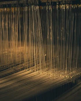
Hollow fiber MBR membranes combine biological treatment with ultrafiltration (0.05–0.4 μm pore size) to achieve 99.9% TSS removal and effluent COD <50 mg/L—meeting EPA 40 CFR Part 503 standards without secondary clarifiers. The system uses thousands of straw-like PVDF fibers (outer diameter 1.2–2.0 mm) submerged in a bioreactor, where aeration scours the membrane surface while permeate is drawn through the fiber walls at flux rates of 15–30 LMH. Unlike flat sheet MBRs, hollow fibers offer 3–5× higher packing density (up to 1,500 m²/m³) and self-supporting structures, reducing footprint by 60% and energy consumption by 20–30% for industrial applications like food processing or pharmaceutical wastewater.
Why Industrial Plants Are Switching to Hollow Fiber MBR: Real-World Cost and Compliance Drivers
Replacing conventional activated sludge (CAS) with hollow fiber MBR allows industrial facilities to increase treatment capacity within the same physical footprint while meeting the world’s most stringent discharge permits. A food processing plant in Shandong recently avoided a $2 million facility expansion by retrofitting its existing tanks with Zhongsheng’s integrated MBR system with PVDF hollow fiber membranes, reducing the total footprint by 60% and consistently achieving effluent COD levels below 50 mg/L. This transition is driven by the failure of gravity-based clarifiers to handle the high-strength organic loads common in modern industrial production.
Compliance requirements such as China GB 18918-2002 Class 1A (TSS <10 mg/L, COD <50 mg/L), EU Directive 91/271/EEC, and EPA 40 CFR Part 503 pathogen limits have made MBR the standard for new builds. In conventional systems, effluent TSS typically fluctuates between 50 and 100 mg/L, requiring expensive tertiary treatment like sand filters or UV disinfection to meet reuse standards. In contrast, hollow fiber MBR produces effluent with <1 mg/L TSS and <1 NTU turbidity. This high-quality permeate is ideal for water reuse applications for MBR effluent, including cooling tower makeup, irrigation, and process water for semiconductor rinse cycles.
The economic driver for MBR adoption is the elimination of the secondary clarifier and the ability to operate at significantly higher biomass concentrations. While CAS systems are limited to 3,000–5,000 mg/L MLSS to prevent sludge bulking in the clarifier, hollow fiber MBR systems operate efficiently at 8,000–12,000 mg/L. This high biomass concentration accelerates biological kinetics, allowing for smaller reactor volumes and the successful treatment of complex industrial streams such as MBR applications for heavy metal wastewater where traditional methods often fall short on compliance.
Hollow Fiber MBR Working Principle: Step-by-Step Process Flow with Engineering Specs
The hollow fiber MBR working principle relies on a "pull" mechanism where a vacuum pump creates a pressure differential across the membrane wall, drawing clean water into the fiber lumen while excluding solids. This process is supported by high-intensity aeration that provides both oxygen for biological activity and mechanical scouring to keep the membrane surface clean. For technical evaluators, understanding the interaction between flux, MLSS, and aeration is critical for system stability.
Step 1: Biological Degradation
The process begins in the bioreactor where mixed liquor suspended solids (MLSS) are maintained between 8,000 and 12,000 mg/L. Microorganisms degrade organic compounds (BOD/COD) and nitrogen species. According to EPA 2024 benchmarks, MBR systems achieve COD removal efficiencies of 92–97% even with influent concentrations ranging from 50 to 500 mg/L. The high sludge age (SRT) in MBRs allows for the growth of nitrifying bacteria that are often washed out of conventional systems.
Step 2: Membrane Filtration
The treated water is drawn through PVDF hollow fiber membranes with a pore size of 0.05–0.4 μm. A vacuum pump maintains a transmembrane pressure (TMP) of 0.1–0.5 bar. In industrial applications, flux rates are typically designed at 15–30 LMH (liters per square meter per hour). This physical barrier is so effective that it removes not only TSS but also most bacteria and viruses, producing a permeate that is technically superior to sand-filtered water.
Step 3: Aeration Scouring
To prevent the formation of a thick sludge cake on the membrane, coarse bubble aeration (0.5–1.0 m³/m²/h) is introduced at the base of the membrane modules. The rising air bubbles create turbulence, causing the flexible hollow fibers to vibrate and rub against each other, physically dislodging accumulated solids. This scouring action is the primary reason why hollow fiber systems consume 0.3–0.6 kWh/m³, which is 20–30% lower than the energy required for flat sheet MBR configurations.
Step 4: Backwashing and Maintenance
Automated maintenance is essential for long-term flux stability. Every 10–30 minutes, the filtration cycle is paused for a 30–60 second backwash. Permeate, sometimes enhanced with 200–500 ppm of sodium hypochlorite (chlorine), is pumped backward through the fibers to clear the pores. Every 3–6 months, a more intensive Maintenance Cleaning (MC) or Recovery Cleaning (RC) is performed using citric acid or NaOH to remove inorganic scaling or organic fouling.
| Engineering Parameter | Standard Range (Industrial) | Unit |
|---|---|---|
| Pore Size | 0.05 – 0.4 | μm |
| MLSS Concentration | 8,000 – 12,000 | mg/L |
| Design Flux (Net) | 15 – 30 | LMH (L/m²/h) |
| Transmembrane Pressure (TMP) | 0.1 – 0.5 | bar |
| Aeration Scour Rate | 0.5 – 1.0 | m³/m²/h |
| Specific Energy Consumption | 0.3 – 0.6 | kWh/m³ |
| Fiber Outer Diameter | 1.2 – 2.0 | mm |
Hollow Fiber vs. Flat Sheet MBR: 2025 Comparison Matrix for Industrial Applications
Selecting the correct membrane geometry is a critical decision that impacts the 10-year Total Cost of Ownership (TCO). While both configurations achieve similar effluent quality, their mechanical structures lead to different operational profiles. Hollow fiber modules consist of thousands of flexible strands potted in epoxy resin, offering massive surface area in a small volume, whereas flat sheet modules consist of rigid panels that are more resistant to "ragging" but require more space and energy.
| Parameter | Hollow Fiber MBR | Flat Sheet MBR | Notes |
|---|---|---|---|
| Packing Density | 500 – 1,500 m²/m³ | 100 – 300 m²/m³ | HF is 3-5x more compact |
| Flux Rate (Industrial) | 15 – 30 LMH | 10 – 25 LMH | HF typically handles higher flux |
| Energy Consumption | 0.3 – 0.6 kWh/m³ | 0.5 – 0.8 kWh/m³ | HF is 20-30% more efficient |
| CAPEX | $1,200 – $2,000/m³/d | $1,500 – $2,500/m³/d | HF has lower initial cost |
| OPEX | $0.20 – $0.40/m³ | $0.30 – $0.50/m³ | HF saves on energy/chemicals |
| Membrane Lifespan | 5 – 8 Years | 7 – 10 Years | FS is more mechanically robust |
| Cleaning Requirement | Frequent Backwash | Chemical Soak Only | HF requires automated backwash |
Decision Tree for Membrane Selection:
- Footprint is the primary constraint (e.g., urban plants or indoor retrofits).
- Energy costs are high and OPEX reduction is a priority.
- The wastewater is well-screened (<1 mm) and has low oil/grease content.
- High-flow applications where CAPEX must be minimized.
- Wastewater contains high concentrations of "rags," hair, or fibrous materials.
- The sludge is highly viscous or has a high oil/grease content (>500 mg/L).
- Operating staff has limited experience with automated backwash systems.
Zero-Risk Selection Framework: How to Specify a Hollow Fiber MBR System for Your Plant
Engineering a successful MBR system requires moving beyond generic flux claims and focusing on the specific chemistry of your influent. A "zero-risk" approach involves validating pre-treatment, calculating flux based on peak loads, and ensuring the membrane material is compatible with your cleaning chemicals. This framework ensures the system integrates seamlessly into a full integrated wastewater treatment plant design.
Step 1: Define Influent Characteristics
Hollow fiber membranes are sensitive to oils and physical debris. If your influent has oil and grease concentrations exceeding 500 mg/L, you must specify DAF pre-treatment for high-oil/grease wastewater. Similarly, high COD (>2,000 mg/L) may require a two-stage anaerobic/aerobic process to protect the membranes from rapid organic fouling.
Step 2: Calculate Required Flux
Use the formula: Flux (LMH) = Daily flow (m³/day) / (Membrane area (m²) × 24 hours). For industrial wastewater, target a conservative net flux of 15–25 LMH. Designing at the upper limit (30+ LMH) often leads to exponential fouling rates and increased chemical costs, negating initial CAPEX savings.
Step 3: Select Membrane Material
PVDF is the industry standard due to its high chemical resistance and mechanical strength, offering a 5–8 year lifespan. While PES (Polyethersulfone) membranes may offer slightly higher initial flux, they are more prone to irreversible fouling and chemical degradation. Avoid PP (Polypropylene) for industrial streams, especially if temperatures exceed 40°C.
| Selection Criteria | Requirement / Target | Risk Mitigation |
|---|---|---|
| Pre-treatment | 1 mm Fine Screen | Prevents fiber breakage/ragging |
| Peak Flux Ratio | < 1.2x Average Flux | Prevents pore clogging during surges |
| Membrane Warranty | Minimum 5 Years | Ensures vendor accountability for integrity |
| Fiber Breakage Rate | < 0.1% per year | Maintains effluent turbidity <1 NTU |
Step 4: ROI Calculation
When evaluating the $1,200–$2,000/m³/day CAPEX, engineers must factor in the savings from eliminated sand filters, reduced sludge hauling costs (due to higher SRT), and the value of reclaimed water. In most industrial scenarios, the ROI for a hollow fiber MBR is achieved within 18–30 months compared to a CAS system with tertiary treatment.
Hollow Fiber MBR Troubleshooting: 5 Common Failures and How to Fix Them
System downtime in an MBR plant is usually the result of fouling or mechanical stress. Unlike conventional systems where "bad" sludge simply settles poorly, in an MBR, bad sludge chemistry directly impacts the filtration rate. Operators must monitor Transmembrane Pressure (TMP) as the primary indicator of system health.
Problem 1: Flux Decline (<10 LMH)
Causes usually include organic or inorganic fouling, or operating at excessively high MLSS (>15,000 mg/L). Fix: Increase the scouring aeration to 1.0 m³/m²/h to physically clean the fibers. If TMP remains high, reduce MLSS through increased sludge wasting and perform a chemical clean-in-place (CIP) using NaOH for organic matter.
Problem 2: Fiber Breakage
This is often caused by "ragging" where hair or fibers bypass the screens and wrap around the membrane bundles. Fix: Ensure the installation of a 1 mm fine screening to prevent fiber breakage. Inspect the potting resin annually for cracks; if breakage exceeds 1%, modules should be isolated or replaced to prevent turbidity spikes.
Problem 3: Irreversible Fouling
This occurs when Extracellular Polymeric Substances (EPS) or calcium carbonate scale becomes embedded deep within the membrane pores. Fix: For scaling, use a citric acid wash at pH 2. To manage EPS, add 5–10 mg/L of Powdered Activated Carbon (PAC) or specialized coagulants to the bioreactor to adsorb the sticky polymers before they reach the membrane.
Problem 4: High Transmembrane Pressure (TMP >0.5 bar)
A rapid rise in TMP suggests a cake layer has formed that backwashing cannot remove. Fix: Increase the backwash frequency to every 10 minutes for 30 seconds. If this fails, perform an offline "soak" cleaning with 500 ppm sodium hypochlorite for 2–4 hours to penetrate the cake layer.
Problem 5: Effluent Turbidity (>1 NTU)
Turbidity in the permeate is a definitive sign of a compromised physical barrier. Fix: Perform a "bubble point test" (ASTM D6908) by applying low-pressure air to the permeate side of the module while submerged; bubbles will identify the specific fibers or potting sections that are leaking. Replace or plug the leaking fibers immediately.
Frequently Asked Questions
Q: What is the lifespan of a hollow fiber MBR membrane?
A: Under industrial conditions with proper pre-treatment and cleaning, PVDF hollow fibers last 5–8 years. Lifespan is significantly shortened by exposure to high concentrations of oils, extreme pH (<2 or >12), or insufficient screening which leads to mechanical breakage.
Q: How much energy does a hollow fiber MBR system consume?
A: Energy consumption typically ranges from 0.3 to 0.6 kWh per cubic meter of treated water. Aeration for membrane scouring accounts for approximately 60–70% of this total. Using variable-frequency drives (VFDs) on blowers can reduce energy use by 15% during low-flow periods.
Q: Can hollow fiber MBR treat high-salinity wastewater?
A: Yes, but with caveats. High salinity (>10,000 mg/L NaCl) increases the viscosity of the mixed liquor and reduces oxygen transfer, which can lead to a 30–50% decline in sustainable flux. Specialized salt-tolerant bacteria and lower design flux rates are required.
Q: What pre-treatment is mandatory for hollow fiber MBR?
A: A 1 mm fine screen is mandatory to protect the fibers from mechanical damage and ragging. Additionally, if the wastewater contains free oils or fats >50 mg/L, a DAF system or oil-water separator is required to prevent the "blinding" of the membrane surface.
Q: How often should the membranes be chemically cleaned?
A: Maintenance cleaning (low-concentration backwash) should occur daily or weekly. A full Recovery Cleaning (RC), involving a chemical soak, is typically required every 3 to 6 months depending on the organic loading and the effectiveness of the daily maintenance protocols.