PCB manufacturers face escalating wastewater hauling costs and regulatory fines for copper, nickel, and fluoride violations. Zero Liquid Discharge (ZLD) systems eliminate discharge entirely, achieving 99.9% water recovery through high-shear membrane filtration (e.g., VSEP® RO) and MVR evaporation. For a 500 m³/day PCB plant, ZLD reduces hauling costs by 80% and recovers 95% of dissolved metals for resale, with a 3–5 year ROI. This guide provides 2025 engineering specs, cost breakdowns, and compliance-ready blueprints for implementation.
Why PCB Manufacturers Are Adopting Zero Liquid Discharge (ZLD)
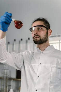
PCB wastewater is a complex cocktail containing copper (50–500 mg/L), nickel (10–100 mg/L), fluoride (20–200 mg/L), and high-molecular-weight organics. According to 2024 EPA and EU ECHA data, approximately 68% of global PCB manufacturing hubs currently operate in regions where these concentrations exceed local discharge limits, leading to frequent permit violations and operational shutdowns.
For plants unable to meet these standards through conventional chemical precipitation, the alternative is "hauling"—transporting hazardous liquid waste to off-site treatment facilities. Industry benchmarks for 2024 show that hauling costs average between $0.50 and $1.20 per gallon. For a mid-sized facility processing 500 m³/day, these fees translate to an annual expenditure of $1.8M to $4.3M. This "disposable" cost provides zero return on investment and scales linearly with production volume, creating a massive drain on OpEx.
Conversely, ZLD systems transform wastewater from a liability into a resource. By integrating copper recovery strategies for semiconductor and PCB wastewater, facilities can generate significant secondary revenue. A 500 m³/day plant can recover between $200,000 and $500,000 worth of high-purity metal annually. This revenue stream typically offsets 30% to 50% of the ZLD system's total operating costs. The regulatory landscape is tightening: China’s GB 8978-1996 mandates copper levels below 0.5 mg/L, while the EU Directive 2010/75/EU sets nickel limits at <1.0 mg/L. ZLD effectively removes the "discharge" variable from the compliance equation entirely.
A shift towards ZLD systems helps manufacturers meet stricter regulations.
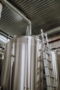
Engineering Blueprint: How ZLD Systems Treat PCB Wastewater
Implementing a ZLD system requires a multi-stage approach to manage the high Total Dissolved Solids (TDS) and complex chemistry of PCB effluent. The engineering blueprint follows a four-stage process designed to maximize water recovery and minimize energy consumption.
Stage 1: Pre-treatment and Solids Removal
The initial stage focuses on removing Total Suspended Solids (TSS) and Fats, Oils, and Grease (FOG) that would otherwise foul downstream membranes. ZSQ series DAF systems for PCB wastewater pre-treatment are utilized here, achieving 92–97% TSS removal. These systems operate at flow rates of 4–300 m³/h, using micro-bubbles to float particulate matter for mechanical skimming.
Stage 2: High-Shear Membrane Filtration
To handle the high-solids environment of PCB waste, high-shear membrane systems like Vibratory Shear Enhanced Processing (VSEP) or high-rejection RO membranes for PCB wastewater ZLD are employed. Unlike traditional RO, which scales quickly under high TDS, high-shear systems maintain flux by creating intense turbulence at the membrane surface. These membranes typically feature pore sizes ranging from 0.001 μm (RO) to 0.1 μm (UF) and achieve over 99% rejection of copper and nickel at operating pressures of 50–100 psi.
Stage 3: Mechanical Vapor Recompression (MVR) Evaporation
The brine from the membrane stage is sent to an MVR evaporator. MVR technology is the "engine" of the ZLD process, concentrating brine to 20–30% solids. By recycling the latent heat of the vapor, MVR systems reduce energy consumption by up to 50% compared to traditional multi-effect evaporators. Engineering specs for these units typically include evaporation rates of 5–20 kg/h/m².
Stage 4: Crystallization and Resource Recovery
The final stage involves a crystallizer or a high-efficiency recovery unit. This step recovers 95% of dissolved copper as 99.9% pure metal. For the remaining solid waste, a sludge dewatering for ZLD brine management system is used to produce a dry "cake" for easier disposal or further processing, ensuring that no liquid leaves the site.
| Component | Technical Specification | Performance Benchmark |
|---|---|---|
| DAF Pre-treatment | Air-to-Solids Ratio: 0.02–0.05 | 97% TSS Removal |
| VSEP/RO Membrane | Pore Size: 0.001–0.1 μm | 99.5% Metal Rejection |
| MVR Evaporator | Heat Transfer Coeff: 2000–4000 W/m²K | 50% Energy Savings vs. MEE |
| Crystallizer | Solids Concentration: 30%–50% | 95% Copper Recovery Yield |
ZLD Cost Breakdown: CapEx, OPEX, and ROI for PCB Plants
Budgeting for a ZLD system requires a transparent look at both the initial capital investment and the long-term operational costs. Based on 2025 industry benchmarks, the CapEx for a ZLD system in a PCB environment ranges from $1.2M for a 100 m³/day facility to $4.5M for a 1,000 m³/day plant. This investment covers the entire process chain: DAF units, membrane modules, MVR evaporators, and crystallization hardware.
The OpEx of a ZLD system is dominated by energy consumption, though MVR technology significantly mitigates this. Average energy costs range from $0.10 to $0.25 per m³ of treated water. Membrane replacement, a critical maintenance item, typically adds $0.05–$0.15 per m³, while labor and chemical dosing for pH adjustment add another $0.08–$0.20 per m³. When compared to the $1.20/gallon cost of hauling, the operational savings are immediate.
The ROI for these systems is typically realized within 3 to 5 years for plants hauling more than 200 m³/day. For a 500 m³/day system, the Internal Rate of Return (IRR) often reaches 20% when accounting for avoided hauling fees and metal recovery revenue.
| Metric | Traditional Treatment | Outsourcing (Hauling) | ZLD System (MVR+RO) |
|---|---|---|---|
| CapEx (500 m³/day) | $0.5M - $0.8M | $0 (Low initial) | $2.5M - $3.2M |
| OpEx (per m³) | $0.40 - $0.60 | $130 - $315 | $0.25 - $0.60 |
| Compliance Risk | High (Fluctuating limits) | Low (Third party) | Zero (Closed loop) |
| Metal Recovery | None (Sludge loss) | None | $200K - $500K / year |
| ROI Period | N/A | N/A | 3.5 Years |
Compliance Checklist: Meeting Global PCB Wastewater Standards with ZLD
Environmental compliance managers must navigate a patchwork of regional standards. ZLD provides a "future-proof" solution because it eliminates the discharge point entirely, but the quality of the internal recycled water must still meet process standards to prevent equipment damage. A comparison of how ZLD effluent matches up against the world's most stringent discharge limits is shown below.
In China, the GB 8978-1996 standard requires copper levels below 0.5 mg/L. ZLD systems typically achieve concentrations of <0.1 mg/L. In the United States, EPA 40 CFR Part 433 sets strict limits on fluoride at <10 mg/L. By utilizing fluoride removal techniques for high-salinity wastewater, ZLD systems can drive fluoride levels below 5 mg/L via the crystallization stage.
| Pollutant | China GB 8978-1996 | EU 2010/75/EU | EPA 40 CFR 433 | ZLD Performance |
|---|---|---|---|---|
| Copper (Cu) | <0.5 mg/L | <0.5 mg/L | <2.3 mg/L | <0.1 mg/L |
| Nickel (Ni) | <1.0 mg/L | <1.0 mg/L | <2.3 mg/L | <0.5 mg/L |
| Fluoride (F) | <10.0 mg/L | N/A | <10.0 mg/L | <5.0 mg/L |
| TDS | <2000 mg/L* | N/A | N/A | <100 mg/L (Permeate) |
*Note: Local China standards vary by province; some mandate lower TDS for sensitive watersheds.
Choosing the Right ZLD System for Your PCB Plant: A Decision Framework
Selecting the appropriate ZLD configuration depends on three primary variables: wastewater volume, chemical complexity, and resource recovery goals. Engineers should follow this step-by-step framework to ensure the system is right-sized for their facility.
Step 1: Characterize the Influent
Conduct a full assay of the waste stream. High concentrations of complexing agents (like EDTA) or surfactants will dictate the type of membrane filtration required. If TSS is above 100 mg/L, a high-efficiency DAF is mandatory to protect the RO stage.
Step 2: Technology Selection (MVR vs. MEE)
For plants processing over 200 m³/day, MVR is almost always the superior choice due to its lower energy footprint. For smaller, boutique PCB shops, Multi-Effect Evaporation (MEE) may have a lower CapEx, though the higher OpEx must be modeled over a 10-year horizon.
Step 3: Metal Recovery Integration
If the copper concentration in the influent exceeds 100 mg/L, a dedicated electrowinning or crystallization module should be prioritized. This transforms the ZLD system from a cost center into a profit-generating asset.
| If Your Plant Has... | Recommended Component | Reasoning |
|---|---|---|