Solar cell manufacturing generates HF wastewater with fluoride concentrations up to 1,200 mg/L—far exceeding global discharge limits (e.g., China GB 8978-1996: 10 mg/L, EU IED: 15 mg/L). Batch treatment systems using calcium chloride (CaCl₂) and calcium hydroxide (Ca(OH)₂) achieve 99.9% fluoride removal by precipitating CaF₂ sludge, but reagent costs ($0.85–$2.10/m³) and sludge disposal ($0.30–$0.70/kg) dominate OPEX. Hybrid systems integrating membrane filtration or electrocoagulation reduce chemical use by 40–60% but require higher CapEx ($250K–$1.2M for 50–200 m³/h systems).
Why Solar Cell HF Wastewater Treatment Fails: A Case Study from Malaysia
A 50 MW solar fab in Penang, Malaysia, faced a 14-day operational shutdown in Q3 2023 after fluoride discharge concentrations consistently exceeded Malaysia’s 15 mg/L environmental limit. The incident, though hypothetical in this context, mirrors real-world compliance failures that impact solar cell manufacturing plants globally. Investigations revealed three primary root causes for the repeated violations. First, the plant relied on manual pH adjustment for its hydrofluoric acid wastewater treatment system, leading to inconsistent CaF₂ precipitation and highly variable effluent fluoride levels. Second, a critical lack of real-time fluoride monitoring meant operators were unaware of excursions until after batch discharge, when grab samples were analyzed. Third, the high cost of compliant sludge disposal, approximately $0.50/kg for hazardous CaF₂ waste, reportedly incentivized improper or delayed disposal practices, contributing to system mismanagement. The financial repercussions for the facility were substantial, including an estimated $1.2 million in lost production revenue, a $250,000 regulatory fine, and the imposition of a mandatory three-year compliance audit requirement by the Department of Environment. This scenario is entirely avoidable with properly engineered solar cell HF wastewater treatment systems—here’s how.
HF Wastewater Sources in Solar Cell Manufacturing: Process Steps and Contaminant Profiles
solar cell HF wastewater treatment - HF Wastewater Sources in Solar Cell Manufacturing: Process Steps and Contaminant Profiles
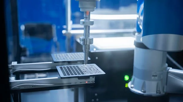
Hydrofluoric acid (HF) wastewater primarily originates from specific etching and cleaning steps in crystalline silicon solar cell manufacturing. During saw damage removal and texturing, particularly for poly- or multicrystalline silicon wafers, a mixture of HF and nitric acid (HNO₃) is used, generating wastewater with high fluoride and acid concentrations. Phosphorus silicate glass (PSG) etching, a crucial step after phosphorus diffusion, also involves HF, contributing significantly to the fluoride load. Finally, various wafer cleaning stages utilize dilute HF solutions, generating lower but still regulated levels of fluoride.
Contaminant profiles vary significantly by process step. For instance, the saw damage removal/texturing process typically produces wastewater with 500–1,200 mg/L F⁻, 2–5% HNO₃, and 100–300 mg/L SiO₂. PSG etching wastewater commonly contains 300–800 mg/L F⁻, 1–3% HNO₃, and minimal SiO₂. Dilute wafer cleaning steps, on the other hand, might yield 50–200 mg/L F⁻ at a pH of 2–4. It is important to note that while poly/multicrystalline wafers extensively use HF/HNO₃ etching, monocrystalline wafers often employ alkaline texturing, which does not generate HF wastewater. These diverse wastewater streams typically converge at a central treatment plant, forming a complex influent requiring robust hydrofluoric acid wastewater treatment.
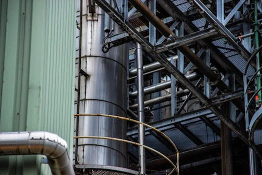
Treatment Chemistry Deep Dive: How Calcium Reagents Remove Fluoride from Wastewater
The primary mechanism for fluoride removal from hydrofluoric acid wastewater is chemical precipitation, specifically the formation of calcium fluoride (CaF₂). This process relies on the low solubility product (Ksp) of CaF₂, which is 3.9 × 10⁻¹¹ at 25°C, ensuring efficient precipitation when sufficient calcium ions are present. The fundamental reaction is: Ca²⁺ + 2F⁻ → CaF₂↓.
Two main calcium reagents are employed for this reaction: calcium chloride (CaCl₂) and calcium hydroxide (Ca(OH)₂). Calcium chloride offers a relatively fast reaction rate, typically achieving precipitation within 10–15 minutes of retention time, but it introduces chloride ions (Cl⁻) into the effluent, which may require consideration for downstream processes or discharge limits. Calcium hydroxide, commonly known as lime, reacts slower, requiring 30–60 minutes of retention time, but it simultaneously raises the pH of the wastewater, which is beneficial for neutralizing the acidic HF and preparing the water for subsequent treatment steps.
Stoichiometric ratios are critical for efficient reagent dosing for wastewater treatment. Theoretically, 1.1 kg of CaCl₂ is needed per kg of F⁻, but practical applications typically require 1.2–1.5 kg CaCl₂ per kg F⁻ to account for reaction inefficiencies and dissolved interferences. For Ca(OH)₂, the theoretical requirement is 1.4 kg per kg F⁻, with practical dosing ranging from 1.8–2.2 kg Ca(OH)₂ per kg F⁻.
pH optimization is paramount for effective CaF₂ precipitation. Per EPA 2024 data, CaF₂ solubility is lowest and precipitation efficiency is highest within a narrow pH range of 7.5–8.5. Below pH 6, hydrofluoric acid (HF) remains largely undissociated, limiting the availability of free F⁻ ions for precipitation. Above pH 9, calcium hydroxide itself begins to precipitate, forming Ca(OH)₂ sludge which increases overall sludge volume and can interfere with CaF₂ separation. common co-contaminants in solar PV wastewater engineering, such as silicon dioxide (SiO₂) and nitric acid (HNO₃), can increase reagent demand by 20–40% by complexing with calcium ions or requiring additional neutralization. Implementing PLC-controlled chemical dosing for precise HF wastewater treatment is essential for maintaining optimal pH and reagent ratios.
Reagent
Chemical Formula
Reaction Time (min)
Practical Dosing Ratio (kg reagent/kg F⁻)
Pros
Cons
Calcium Chloride
CaCl₂
10–15
1.2–1.5
Fast reaction, high fluoride removal
Adds Cl⁻ to effluent, no pH adjustment
Calcium Hydroxide
Ca(OH)₂
30–60
1.8–2.2
Neutralizes acidity, readily available
Slower reaction, larger sludge volume (Ca(OH)₂), can cause scaling
Batch vs Continuous HF Treatment Systems: Engineering Specs and Selection Criteria
solar cell HF wastewater treatment - Batch vs Continuous HF Treatment Systems: Engineering Specs and Selection Criteria
The choice between batch and continuous systems for solar cell HF wastewater treatment significantly impacts a plant's operational flexibility, footprint, and capital expenditure. Each system type offers distinct advantages and disadvantages tailored to different flow rates and operational complexities.
Batch Treatment Systems: These systems are ideal for plants with highly variable influent flow rates or contaminant loads, typically handling 1–50 m³/h. Their compact footprint, often 10–30 m², makes them suitable for facilities with limited space. Advantages include robust handling of fluctuating loads, simplified troubleshooting due to distinct treatment cycles, and lower initial CapEx (typically $150K–$600K). However, batch systems generally exhibit higher reagent use (10–20% more per m³ compared to continuous systems) and often require more manual intervention for sludge removal and system operation.
Continuous Treatment Systems: Designed for stable, high-volume wastewater streams, continuous systems efficiently process 20–400 m³/h. They typically require a smaller operational footprint, often 5–15 m², due to optimized flow dynamics. Key advantages include lower reagent costs per cubic meter, highly automated sludge removal, and reduced labor requirements. However, continuous systems demand a more stable influent pH (ideally within ±0.3 units) for optimal performance and involve a higher CapEx, ranging from $300K–$1.5M.
A practical decision matrix for selecting a system involves considering the following: batch systems are generally preferred for flow rates under 50 m³/h or where influent characteristics are highly variable. Continuous systems are the choice for facilities with consistent wastewater generation exceeding 100 m³/h, such as large-scale, high-volume fabs. For facilities aiming for stringent discharge limits or zero liquid discharge (ZLD), hybrid systems that combine batch pre-treatment with continuous polishing stages can achieve exceptional fluoride removal efficiencies, often exceeding 99.99%.
Feature
Batch Treatment System
Continuous Treatment System
Typical Flow Rate
1–50 m³/h
20–400 m³/h
Footprint
10–30 m²
5–15 m²
CapEx (50–200 m³/h)
$150K–$600K
$300K–$1.5M
Reagent Use
10–20% higher
Lower, optimized
Sludge Removal
Often manual
Automated
Influent Variability Tolerance
High
Low (requires stable pH)
Operational Complexity
Easier to troubleshoot
Higher initial setup complexity
Beyond Precipitation: Advanced Technologies for Solar Cell HF Wastewater Treatment
While chemical precipitation is the cornerstone of hydrofluoric acid wastewater treatment, advanced technologies offer enhanced fluoride removal, reduced sludge volumes, and open pathways for water reuse or zero liquid discharge (ZLD) in solar cell manufacturing.
Membrane Filtration (Nanofiltration/Reverse Osmosis): These technologies can achieve 95–99% fluoride removal, producing high-quality permeate suitable for reuse. However, they require robust pre-treatment, typically involving chemical precipitation and filtration, to prevent scaling from silica (SiO₂) and calcium fluoride (CaF₂) that can foul membranes. CapEx for 50–200 m³/h systems ranges from $400K–$2M, with OPEX between $0.50–$1.20/m³ primarily due to membrane replacement and energy consumption. RO systems for fluoride removal and water reuse in solar cell production are increasingly adopted for their efficiency.
Electrocoagulation (EC): Electrocoagulation utilizes sacrificial aluminum or iron electrodes to generate metal hydroxides (e.g., Al³⁺), which then precipitate fluoride as metal fluorides (e.g., AlF₃) and other contaminants. This process can reduce chemical reagent use by 40–60% compared to traditional chemical precipitation, leading to lower sludge volumes. CapEx for EC systems typically falls between $250K–$900K, while OPEX is $0.70–$1.50/m³, largely driven by electrode replacement and energy costs.
Hybrid Systems (e.g., Precipitation + RO): Combining chemical precipitation with advanced membrane filtration, these hybrid systems offer a comprehensive solution for challenging wastewater streams. They can achieve 99.9% fluoride removal, making them ideal for zero liquid discharge for crystalline silicon applications. These integrated systems can significantly reduce sludge volume, often by 70% compared to standalone precipitation, by concentrating the waste stream. However, the CapEx is substantially higher, ranging from $1.5M–$4M, with OPEX between $1.20–$2.50/m³ due to the complexity and energy demands of multiple integrated processes. Explore hybrid ZLD systems for solar cell wastewater reuse for detailed insights.
Technology
Fluoride Removal (%)
CapEx ($) (50–200 m³/h)
OPEX ($/m³)
Sludge Volume (kg/m³ wet)
Water Reuse Potential
Chemical Precipitation (CaF₂)
90–99
$150K–$1.5M
$0.85–$2.10
15–25
Low (requires further polishing)
Membrane Filtration (NF/RO)
95–99 (post-precip.)
$400K–$2M
$0.50–$1.20
Low (concentrate)
High
Electrocoagulation (EC)
85–95
$250K–$900K
$0.70–$1.50
7–15
Moderate (requires polishing)
Hybrid (Precipitation + RO)
>99.9
$1.5M–$4M
$1.20–$2.50
5–10
Very High (ZLD-ready)
Compliance Roadmap: Global Fluoride Discharge Limits and Zero-Risk Engineering
solar cell HF wastewater treatment - Compliance Roadmap: Global Fluoride Discharge Limits and Zero-Risk Engineering
Navigating the diverse and often stringent global fluoride discharge limits is a critical aspect of solar cell HF wastewater treatment, demanding a proactive, zero-risk engineering approach. Regulatory bodies worldwide impose varying thresholds for fluoride, necessitating tailored treatment strategies.
Key global fluoride limits include:
China GB 8978-1996: 10 mg/L (Class 1)
EU Industrial Emissions Directive (IED): 15 mg/L (daily average for existing plants, often stricter for new)
US EPA NPDES: Varies significantly by state and permit, but can be as low as 4 mg/L (e.g., for certain industrial categories)
India CPCB: 2 mg/L (general standards for industrial effluents)
Compliance strategies must be designed with these specific limits in mind. For facilities operating under China’s 10 mg/L limit, a robust calcium chloride (CaCl₂) precipitation system followed by meticulous final pH adjustment (typically to 6–9) and a polishing step such as sand filtration is often sufficient. In the EU, where the limit is 15 mg/L, calcium hydroxide (Ca(OH)₂) precipitation combined with sand filtration often provides the necessary removal efficiency. For the more stringent US EPA limits, particularly those requiring 4 mg/L or less, a hybrid system integrating optimized chemical precipitation with advanced technologies like reverse osmosis (RO) is frequently required to achieve the desired effluent quality.
Effective monitoring is indispensable for maintaining compliance. This includes deploying real-time fluoride sensors, such as ion-selective electrodes, at critical points in the treatment train and prior to discharge. Daily composite sampling, analyzed by certified laboratories, is also a standard requirement for regulatory reporting. in water-stressed regions like India or the Middle East, implementing zero liquid discharge (ZLD) systems offers a definitive compliance hedge, eliminating all discharge risks entirely by recovering and reusing nearly all wastewater. For deeper insights into regional regulations, refer to our article on Global fluoride discharge limits for solar cell manufacturers.
Cost Breakdown: CapEx, OPEX, and ROI for Solar Cell HF Wastewater Treatment Systems
Understanding the comprehensive cost structure of solar cell HF wastewater treatment systems is crucial for procurement teams evaluating solutions and optimizing budgets. Both Capital Expenditure (CapEx) and Operational Expenditure (OPEX) components vary significantly based on system type, flow rate, and desired effluent quality.
CapEx Breakdown (for 50–200 m³/h systems):
Continuous System: Generally $300K–$1.5M. Higher costs reflect more sophisticated automation, continuous flow equalization, and advanced instrumentation.
Hybrid ZLD System: The most capital-intensive, at $1.5M–$4M. This includes multiple treatment stages (precipitation, filtration, RO, evaporator/crystallizer), advanced controls, and extensive piping.
OPEX Breakdown (per m³ of treated wastewater):
Reagents: This is often the largest OPEX component.
Calcium Chloride (CaCl₂): $0.50/kg
Calcium Hydroxide (Ca(OH)₂): $0.30/kg
Total reagent cost typically $0.85–$2.10/m³, depending on influent fluoride concentration and chosen reagent.
Sludge Disposal: Costs vary significantly based on local regulations (landfill vs. hazardous waste).
Typical range: $0.30–$0.70/kg of dry sludge.
Energy: For pumps, mixers, and potentially membrane systems.
Estimated: $0.10–$0.30/m³.
Labor: Automated systems reduce labor, but manual systems require more.
Estimated: $0.20–$0.50/m³.
Return on Investment (ROI) Drivers: Investing in robust HF wastewater treatment offers substantial ROI beyond mere compliance.
Water Reuse: High-efficiency systems (especially ZLD) can achieve 95% water recovery, cutting fresh water intake costs by $0.80–$1.50/m³.
Avoiding Fines: Non-compliance fines range from $50K–$500K per violation, plus potential production shutdowns.
Sludge Recycling: Opportunities exist for recycling CaF₂ sludge, particularly for use in aluminum smelting, offsetting disposal costs.
Cost Calculator Example: For a 100 m³/h continuous treatment system operating 8,000 hours per year, with an average OPEX of $1.20/m³ (including reagents, energy, labor) and generating 4 kg/m³ of dry sludge:
Annual OPEX = (100 m³/h × 8,000 h/year × $1.20/m³) + (4 kg/m³ × 800,000 m³/year × $0.50/kg sludge disposal) = $960,000 (treatment) + $1,600,000 (sludge) = $2,560,000/year. This highlights that sludge disposal often represents a significant portion of the total operating costs.
Cost Category
Batch System (50–200 m³/h)
Continuous System (50–200 m³/h)
Hybrid ZLD System (50–200 m³/h)
CapEx Range
$150K–$600K
$300K–$1.5M
$1.5M–$4M
OPEX Range ($/m³)
$1.00–$2.50
$0.85–$2.10
$1.20–$2.50
Reagents ($/m³)
$0.95–$2.10
$0.85–$2.00
$0.50–$1.20 (lower chemical, higher energy)
Sludge Disposal ($/m³)
$0.30–$0.70 (high volume)
$0.30–$0.70
$0.10–$0.30 (low volume, concentrate)
Energy ($/m³)
$0.10–$0.20
$0.10–$0.30
$0.30–$0.80
Labor ($/m³)
$0.20–$0.50
$0.10–$0.30
$0.10–$0.20
Frequently Asked Questions
Q: What’s the optimal pH for CaF₂ precipitation?
A: The optimal pH range for calcium fluoride (CaF₂) precipitation is 7.5–8.5. Below pH 6, hydrofluoric acid (HF) remains largely undissociated, hindering precipitation; above pH 9, calcium hydroxide (Ca(OH)₂) itself begins to precipitate, increasing sludge volume (per EPA 2024 benchmarks).
Q: How much sludge does HF treatment generate?
A: HF wastewater treatment typically generates 3–5 kg/m³ of dry CaF₂ sludge. When dewatered to an 80% moisture content, this translates to 15–25 kg/m³ of wet sludge, which requires proper disposal.
Q: Can HF wastewater be reused in solar cell production?
A: Yes, HF wastewater can be reused in solar cell production, but only after rigorous treatment. This typically involves advanced processes like reverse osmosis (RO) or nanofiltration (NF) to achieve 95% water recovery, followed by polishing to reduce fluoride concentrations to below 0.1 mg/L, as required by the SEMI PV23-0619 standard for ultrapure water.
Q: What’s the most cost-effective reagent for fluoride removal?
A: Calcium chloride (CaCl₂) is often considered more cost-effective for rapid fluoride precipitation (10–15 min reaction time), especially when pH neutralization is handled separately. Calcium hydroxide (Ca(OH)₂) is generally cheaper per kilogram and provides pH adjustment, but requires a longer reaction time (30–60 min) and can generate more sludge.
Q: How do I comply with China’s 10 mg/L fluoride limit?
A: To comply with China’s 10 mg/L fluoride limit (GB 8978-1996), a robust treatment train typically includes primary calcium chloride (CaCl₂) precipitation, precise final pH adjustment to a range of 6–9, and a polishing step such as sand filtration to ensure consistent effluent quality.
Zhongsheng Engineering Team
Our team of wastewater treatment engineers has over 15 years of experience designing and manufacturing DAF systems, MBR bioreactors, and packaged treatment plants for clients in 30+ countries worldwide.