A tube settler clarifier is an inclined-plate sedimentation system that increases the effective settling area of a clarifier by 3–5×, reducing footprint by up to 70% while achieving 92–97% TSS removal at influent turbidity levels of 50–500 NTU (per EPA 2024 benchmarks). By forcing water through 60°-angled PVC or PP tubes (spacing: 50–80 mm), suspended particles collide with tube surfaces and settle faster under gravity—cutting hydraulic retention time from 2–4 hours (conventional clarifiers) to 30–60 minutes. Ideal for industrial wastewater with high solids loading, tube settlers are used in food processing, pulp & paper, and municipal plants to meet discharge limits like China GB 8978-1996 (<70 mg/L TSS) or EU Urban Waste Water Directive 91/271/EEC (<35 mg/L).
Why Industrial Plants Struggle with Conventional Clarifiers
Conventional clarifiers require a hydraulic retention time (HRT) of 2–4 hours to achieve 80–90% TSS removal, which often leads to massive civil engineering costs and operational inefficiencies (per EPA 2023 data). For a standard industrial flow of 100 m³/h, a conventional circular clarifier typically requires a footprint of approximately 100 m². With 2025 construction data estimating civil costs at $50–$150/m², the land and infrastructure investment alone can become a project bottleneck. these systems rely heavily on gravity settling over large vertical distances, which is inherently slow and susceptible to thermal currents and hydraulic surges.
To compensate for slow settling rates, many plant managers increase chemical dosing. Flocculant and coagulant costs for conventional systems range from $0.10–$0.30/m³ in OPEX. This high chemical demand not only increases the cost per gallon treated but also results in higher sludge volumes, compounding disposal issues. A real-world example of these limitations was seen at a textile plant in Bangladesh, which utilized a 4-hour HRT clarifier. Despite the large footprint, the plant only reduced TSS from 120 mg/L to 85 mg/L, failing to meet the local regulatory limit of 70 mg/L without the addition of expensive tertiary filtration.
The reliance on large-volume tanks also makes upgrades difficult. When an industrial facility needs to increase capacity due to production growth, a conventional clarifier setup offers no "vertical" scalability. Engineers are forced to build additional tanks, which may not be feasible in space-constrained urban or brownfield sites. This lack of intensity in the sedimentation process is the primary driver for the transition toward high-rate clarification technologies like tube settlers.
How Tube Settler Clarifiers Work: Engineering Mechanics
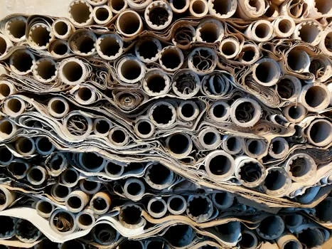
Tube settlers operate on the principle of shallow-depth sedimentation, which reduces the vertical distance a particle must travel before it is "captured" from 1.5–3 meters in conventional tanks to just 50–100 mm. The core of the system is a stack of 60°-angled tubes (typically PVC or PP) that create multiple parallel settling channels. As influent water moves upward through these tubes, suspended solids settle onto the tube surface. Once the accumulated floc gains sufficient mass, it slides down the 60° incline against the flow of water and falls into the sludge hopper below.
The engineering physics behind this efficiency is rooted in Stokes’ Law. By providing a large surface area in a small volume, tube settlers ensure that the Reynolds number remains below 500, maintaining laminar flow. This laminar environment is critical because it prevents the re-suspension of settled particles. The hydraulic loading rate (HLR) for these systems is significantly higher than conventional counterparts, ranging from 20–40 m/h, compared to the 1–2 m/h typical of basic gravity settlers.
| Engineering Parameter | Standard Specification | Impact on Performance |
|---|---|---|
| Tube Angle | 60° (Fixed) | Optimal balance between particle capture and sludge self-cleaning. |
| Tube Spacing/Opening | 50 mm – 80 mm | Prevents clogging while maximizing effective settling area. |
| Wall Thickness | 1.0 mm – 2.0 mm | Ensures structural integrity under hydraulic pressure and sludge weight. |
| Material | PVC / PP / HDPE | Chemical resistance and temperature tolerance (up to 90°C for HDPE). |
| Hydraulic Loading Rate | 20 – 40 m/h | Allows for 10x higher flow through the same footprint vs. conventional. |
The process flow begins with the influent entering a flocculation zone where automated chemical dosing for optimal flocculation aggregates fine particles into larger flocs. The water then enters the bottom of the tube settler modules. The "V" shaped or hexagonal tube geometry forces the water through a tortuous path, increasing collision frequency between particles and tube walls. The clarified effluent is then collected by a series of V-notch weirs at the surface, while the sludge is concentrated in a conical hopper for removal.
Tube Settler vs. Plate Settler vs. Conventional Clarifier: Performance Comparison
Choosing between sedimentation technologies requires a trade-off analysis of efficiency, footprint, and cost. While plate settlers (lamella plates) offer high efficiency, they often carry a higher CAPEX due to the stainless steel or heavy plastic plate construction. Tube settlers provide a middle ground, offering similar efficiency to plate settlers but at a lower price point and with easier installation in circular tanks.
| Parameter | Tube Settler | Plate Settler | Conventional Clarifier |
|---|---|---|---|
| TSS Removal Efficiency | 92–97% | 85–92% | 80–90% |
| Footprint Reduction | 70% | 60% | 0% (Baseline) |
| Hydraulic Loading Rate (m/h) | 20–40 | 10–20 | 1–2 |
| CAPEX ($/m³/h) | $1,200–$2,500 | $1,500–$3,000 | $800–$1,800 |
| OPEX ($/m³) | $0.02–$0.05 | $0.03–$0.07 | $0.05–$0.15 |
| Maintenance Frequency | Quarterly (Cleaning) | Monthly (Inspection) | Annual (Desludging) |
Tube settlers outperform conventional clarifiers in OPEX primarily through chemical savings and reduced energy requirements for sludge pumping. Because the settling is more efficient, less coagulant is needed to achieve the same effluent quality. While maintenance for tube settlers is more frequent than for conventional tanks—requiring periodic hosing down to prevent biofilm or sludge accumulation—the overall lifecycle cost is significantly lower due to the reduced footprint and civil works requirements.
Engineering Specs: How to Select the Right Tube Settler for Your Wastewater
The selection of a tube settler system is not a one-size-fits-all process; it requires a detailed understanding of the influent characteristics and the target discharge limits. Engineers must first characterize the influent, focusing on TSS, turbidity, and particle size distribution. For example, in applications where TSS exceeds 300 mg/L, a wider tube spacing of 80 mm is recommended to prevent bridging and clogging within the modules.
The second step involves calculating the required surface area. The surface loading rate is determined by dividing the flow rate (m³/h) by the projected area (m²). For a 100 m³/h flow, targeting a 20–40 m/h loading rate would require a projected area of only 2.5–5 m². This calculation is vital to ensure the system remains in a laminar flow regime. the choice of material must align with the wastewater temperature and pH. PVC is cost-effective for standard applications under 60°C, while PP or HDPE should be specified for high-temperature or chemically aggressive industrial streams.
| Regulatory Target | Required Removal | Tube Specification Recommendation |
| China GB 8978-1996 (<70 mg/L TSS) | 95% | 60 mm spacing, 1.0m tube length |
| EU Directive 91/271/EEC (<35 mg/L) | 97% | 50 mm spacing, 1.2m tube length |
| Pre-RO Treatment (<5 NTU) | 99% | 50 mm spacing + tertiary filtration |
Sizing the sludge hopper is the final critical step. For a typical industrial sludge with 5% solids content, the hopper volume should be calculated as 0.05 × flow rate × retention time. For a 100 m³/h system with a 1-hour retention time, a 5 m³ hopper is required to prevent sludge overflow back into the tube modules. To ensure high performance, engineers often consider Zhongsheng’s lamella clarifier with tube settler modules for integrated design. For those looking at the full process chain, it is helpful to understand how to select filter media for downstream filtration after tube settlers to meet ultra-low discharge limits.
Decision Framework Flowchart:
Start → Measure Influent TSS → Is TSS > 500 mg/L? → (If Yes: Add pre-sedimentation/grit removal) → (If No: Select 50-80 mm tube spacing) → Calculate projected surface area based on HLR (20-40 m/h) → Select material based on temp/pH → Verify sludge hopper volume → Ensure compliance with local TSS limits.
Real-World Efficiency: Tube Settler Performance Data from Industrial Plants
Industrial data from a pulp and paper mill in Indonesia demonstrates that tube settlers can achieve 92% TSS removal and 75% COD removal while reducing footprint by 65%. In this specific case, the influent TSS was 450 mg/L and COD was 1,200 mg/L. After upgrading their conventional clarifier with tube settler modules, the effluent TSS dropped to 35 mg/L and COD to 300 mg/L. This improvement allowed the mill to reduce its flocculant dosing by 30%, resulting in a chemical saving of $0.08/m³.
In the United States, a food processing plant faced challenges with high Fats, Oils, and Grease (FOG) and TSS. By implementing a tube settler system with a hydraulic loading rate of 35 m/h, the plant reduced influent TSS from 220 mg/L to 18 mg/L (92% removal) and FOG from 150 mg/L to 25 mg/L (83% removal). The compact design allowed the plant to install the treatment system inside an existing building, saving significant costs on new facility construction.
Municipal wastewater treatment plants (WWTPs) in China have also adopted this technology to meet the stringent GB 18918-2002 standards. A plant in Jiangsu Province reported an influent turbidity of 120 NTU and TSS of 180 mg/L. After the installation of tube settlers, the effluent turbidity was consistently below 5 NTU (96% removal) and TSS below 12 mg/L (93% removal). This performance allowed the plant to bypass the need for expensive tertiary sand filters while still meeting Grade A discharge standards.
Cost Breakdown: Tube Settler CAPEX, OPEX & ROI Calculation
The total CAPEX for a tube settler system in 2025 ranges from $1,200 to $2,500 per m³/h of capacity, offering a payback period of 1.5 to 3 years compared to conventional systems. This CAPEX includes the tube modules ($800–$1,500/m³ depending on material), the structural support frame in stainless or coated carbon steel ($200–$500/m²), and installation labor. For a 100 m³/h system, the total investment typically falls between $120,000 and $250,000.
OPEX is remarkably low, averaging $0.02–$0.05/m³. This includes energy for sludge pumps ($0.005–$0.01/m³), reduced chemical costs compared to conventional tanks, and maintenance labor for quarterly cleaning. When calculating ROI, the primary drivers are the reduction in chemical consumption and the avoidance of regulatory fines. In a sensitivity analysis, the payback period for a 100 m³/h system remains under 4 years even if chemical savings are 20% lower than projected or if CAPEX increases by 15%.
| Cost Category | Estimated Cost (2025) | Notes |
|---|---|---|
| Tube Modules | $800 – $1,500 per m³ | PVC is cheaper; PP/HDPE for high temp. |
| Structural Frame | $200 – $500 per m² | 304/316 Stainless Steel is standard. |
| Installation | $150 – $300 per m² | Includes civil work and module assembly. |
| Annual Maintenance | $0.005 – $0.01 per m³ | Quarterly cleaning and inspections. |
Beyond financial metrics, the non-financial ROI is significant. The smaller footprint allows for future plant expansion without land acquisition, and the high removal efficiency ensures consistent compliance with environmental permits. For plants considering the full sludge management cycle, it is useful to review the cost comparison of sludge thickening technologies for tube settler underflow to optimize the final disposal costs.
Common Failure Modes & Troubleshooting Guide
Clogging is the most frequent failure mode in tube settlers, often caused by TSS levels exceeding 500 mg/L or inadequate pre-treatment flocculation. When tubes clog, the hydraulic capacity drops and effluent TSS rises as water "short-circuits" around the blocked areas. The solution is to increase tube spacing to 80 mm for high-solids applications or to install an air scouring system (0.5–1 m³/m²·h) that periodically vibrates the tubes to release accumulated sludge.
Hydraulic short-circuiting is another common issue, usually resulting from poor inlet design or damaged tube modules. If water enters the settler unevenly, it creates high-velocity zones that carry floc over the effluent weirs. Operators should check for damaged or warped tubes and ensure that flow distributors at the inlet are clear of debris. Regular adjustment of the sludge withdrawal rate is also necessary to prevent a "sludge blanket" from rising into the tube zone.
Material degradation can occur if the wrong polymer is selected for the wastewater chemistry. PVC can become brittle and crack if exposed to high UV radiation in outdoor tanks or if the water temperature exceeds 60°C. In such cases, replacing the modules with HDPE or PP is the only long-term fix. Finally, scaling caused by high calcium or magnesium hardness can coat the tubes, reducing settling efficiency. This can be mitigated by pre-treating the water with lime softening or implementing a monthly acid wash (pH 2–3) to dissolve mineral deposits.
Frequently Asked Questions
Q: What is the optimal tube angle for a tube settler clarifier?
A: 60° is the industry standard. This angle balances particle capture efficiency (92–97% TSS removal) with the ability of the sludge to slide down the tube surface under its own weight. Angles less than 55° significantly increase the risk of clogging, while angles greater than 65° reduce the effective horizontal settling area.
Q: Can tube settlers handle high-turbidity wastewater (>1,000 NTU)?
A: Yes, but pre-treatment is critical. For turbidity levels exceeding 1,000 NTU, a grit chamber or pre-sedimentation tank should be used to reduce the solids load to below 500 mg/L before the water enters the tube settlers. A mining plant in Chile successfully achieved 95% TSS removal at 1,200 NTU using this two-stage approach.
Q: How often should tube settlers be cleaned?
A: Quarterly cleaning is sufficient for most industrial applications where TSS is below 300 mg/L. For high-solids environments, monthly cleaning using low-pressure water jets (2–3 bar) or integrated air scouring is recommended to prevent biofilm growth and sludge bridging.
Q: Are tube settlers suitable for cold climates (<10°C)?
A: Yes, but material selection is key. PVC can become brittle at temperatures below 5°C. For cold-weather installations, HDPE or PP modules are preferred as they maintain structural integrity down to -20°C. A Scandinavian paper mill maintained 94% TSS removal at 4°C using HDPE modules.
Q: What is the lifespan of a tube settler module?
A: Typically 10–15 years for PVC and PP, and up to 20 years for HDPE. The lifespan is heavily dependent on chemical exposure, UV protection, and the gentleness of the cleaning process. Modules should be inspected annually and replaced if more than 10% of the tubes show signs of warping or cracking.