Photovoltaic HF Wastewater Treatment: 2025 Engineering Specs, 99.9% Fluoride Removal & Cost Breakdown
Photovoltaic (PV) manufacturing generates hydrofluoric acid (HF) wastewater with fluoride concentrations ranging from 10 mg/L to 10,000 mg/L, far exceeding China GB 31573-2015 limits (<10 mg/L). Calcium salt precipitation is the most proven method for PV HF wastewater treatment, achieving 99.9% fluoride removal when optimized for pH (10–12), reaction time (30–60 minutes), and calcium-to-fluoride molar ratios (1.2:1 to 1.5:1). Hybrid zero liquid discharge (ZLD) systems combining precipitation with membrane filtration or adsorption can further reduce fluoride to <1 mg/L, enabling water reuse and compliance with global standards like EPA 40 CFR Part 420 and EU Industrial Emissions Directive 2010/75/EU.
Why PV Factories Struggle with HF Wastewater: A Regulatory and Operational Crisis
China GB 31573-2015 mandates a fluoride discharge limit of <10 mg/L for the photovoltaic industry, a threshold that presents a massive technical hurdle given that raw HF wastewater from texturing and etching processes often exceeds 5,000 mg/L. Non-compliance is not merely an environmental concern but a financial liability; under current Chinese environmental laws, a 1 GW PV factory discharging 500 m³/day of HF wastewater at high concentrations faces annual fines estimated at $200,000, alongside the risk of mandatory production halts.
The operational risks associated with hydrofluoric acid are equally severe. HF is highly corrosive, capable of degrading standard stainless steel and concrete infrastructure within months if not properly neutralized. For EHS managers, the primary concern is the safety of personnel, as HF exposure causes deep tissue damage and systemic toxicity. From an engineering perspective, the high variability of fluoride concentrations—fluctuating between 10 mg/L in rinse water to 10,000 mg/L in spent etch baths—demands a treatment system with extreme buffering capacity and automated response. Failure to manage these fluctuations leads to "fluoride spikes" in the final effluent, triggering regulatory alarms and potentially fouling downstream RO systems for PV HF wastewater reuse.
The high concentration of silicon and other non-metallic ions in PV wastewater complicates the defluorination process. These ions can interfere with the crystallization of calcium fluoride (CaF2), resulting in fine, non-settling flocs that escape traditional clarifiers. This operational instability often forces plants to over-dose chemicals, leading to excessive sludge production and skyrocketing OPEX. Achieving a consistent 99.9% removal rate requires a deep understanding of the chemical equilibrium between fluoride and calcium ions under specific industrial conditions (HydropureWater field data, 2025).
Treatment Methods for PV HF Wastewater: Engineering Specs and Removal Efficiencies

Selecting the appropriate treatment technology depends on the influent fluoride concentration, required discharge limits, and the potential for water reclamation. Calcium salt precipitation remains the industry standard for high-concentration streams, while adsorption and membrane processes are used for polishing.
Calcium Salt Precipitation (Ca(OH)₂ and CaCl₂): This process relies on the low solubility of calcium fluoride (Ksp = 3.45 x 10⁻¹¹ at 25°C). To achieve 99.9% removal, engineers must maintain a pH between 10 and 12. At this range, the solubility of CaF2 is minimized. A calcium-to-fluoride molar ratio of 1.2:1 to 1.5:1 is required to drive the reaction to completion. Reaction times of 30–60 minutes in a multi-stage stirred tank reactor ensure adequate crystal growth. The resulting sludge must be managed using a sludge dewatering for calcium salt precipitation system to reduce disposal volumes.
Adsorption: Utilizing activated alumina or specialized ion-exchange resins, adsorption is highly effective for low-concentration wastewater (<100 mg/L). While it can achieve fluoride levels <1 mg/L, the media requires frequent regeneration with sulfuric acid or sodium hydroxide, which increases OPEX. It is best suited as a tertiary polishing step following precipitation.
Membrane Filtration (RO/NF): Reverse Osmosis (RO) and Nanofiltration (NF) provide a physical barrier to fluoride ions. However, in PV applications, the high silica content and calcium hardness pose a significant risk of RO membrane fouling prevention challenges. Pretreatment, including softening and ultrafiltration, is mandatory to maintain membrane flux and longevity.
| Treatment Method | Optimal Influent [F-] | Removal Efficiency | Key Engineering Parameters | Primary Advantage |
|---|---|---|---|---|
| Calcium Precipitation | 500 - 10,000 mg/L | 95% - 99.9% | pH 10-12; 1.3:1 Ca:F Ratio | Low CAPEX, handles high loads |
| Adsorption (Alumina) | 10 - 100 mg/L | 90% - 98% | SV 5-10 h⁻¹; pH 5.5-6.5 | Achieves <1 mg/L discharge |
| Reverse Osmosis (RO) | <50 mg/L | 95% - 99% | Flux 15-20 LMH; <3 SDI | Enables high-quality water reuse |
| Electrocoagulation | 50 - 500 mg/L | 90% - 95% | 20-40 A/m²; 2-4 kWh/m³ | No chemical sludge; compact |
For large-scale PV manufacturing, a single-stage treatment is rarely sufficient. Most modern facilities utilize a dual-stage precipitation process: the first stage uses lime (Ca(OH)₂) for bulk removal and pH adjustment, while the second stage uses calcium chloride (CaCl₂) and a precise chemical dosing for PV HF wastewater treatment to reach the final compliance targets. This approach balances chemical costs with removal precision.
Hybrid ZLD Systems for PV HF Wastewater: Design, Recovery Rates, and Cost Breakdown
To meet the growing demand for sustainable manufacturing, hybrid ZLD systems for PV wastewater have become the gold standard. These systems integrate chemical, physical, and membrane processes to achieve 99.9% fluoride removal and up to 95% water recovery. The typical process flow starts with two-stage calcium precipitation, followed by sand filtration and ultrafiltration (UF) to protect the RO membranes.
The performance of these systems is measured by their ability to maintain a stable effluent of <1 mg/L fluoride despite massive influent fluctuations. In a 100 m³/day system, the CAPEX typically ranges from $500,000 to $2,000,000, depending on the degree of automation and the inclusion of evaporation units for true zero liquid discharge. OPEX is driven primarily by chemical consumption (lime and coagulants) and energy for membrane pumping, usually averaging $2 to $5 per cubic meter of treated water.
| Cost/Performance Metric | Standard Precipitation | Hybrid ZLD System |
|---|---|---|
| Fluoride Removal Rate | 98.5% | 99.9% |
| Water Recovery Rate | 0% (Discharge only) | 85% - 95% |
| CAPEX (100 m³/day) | $150,000 - $300,000 | $500,000 - $2,000,000 |
| OPEX ($/m³) | $0.80 - $1.50 | $2.00 - $5.00 |
| ROI (Years) | N/A (Compliance only) | 3.5 - 5.0 Years |
The Return on Investment (ROI) for a ZLD system in a 1 GW PV factory is increasingly attractive. By recovering 90% of the wastewater, a factory can save approximately $150,000 annually in raw water procurement costs. When combined with the avoidance of environmental fines and reduced sludge disposal costs through high-efficiency sludge dewatering for calcium salt precipitation, the system typically pays for itself within 42 months.
Compliance Checklist: China GB 31573-2015 and Global Standards for PV Wastewater
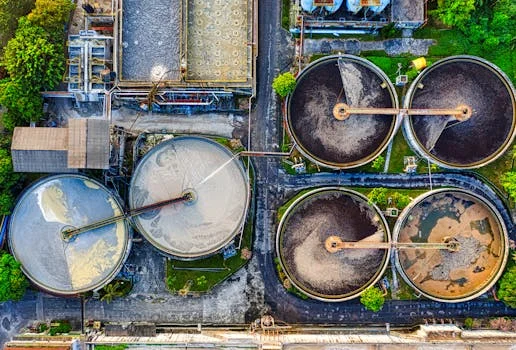
Navigating the global discharge standards for PV wastewater requires a tiered approach to compliance. While China GB 31573-2015 is the primary benchmark for many manufacturers, global players must also adhere to EPA and EU standards if they operate or export to those regions.
- Fluoride Concentration: Ensure effluent is consistently <10 mg/L (GB 31573) or <4 mg/L (EPA 40 CFR Part 420 for direct discharge).
- pH Stabilization: Effluent must be neutralized to a range of 6.0–9.0 before discharge, requiring an automated acid/base dosing loop.
- Chemical Oxygen Demand (COD): PV wastewater often contains IPA (Isopropanol), which can push COD above the 100 mg/L limit. Advanced oxidation or biological treatment may be required.
- Total Suspended Solids (TSS): To prevent turbidity issues, TSS must be kept below 50 mg/L, necessitating high-efficiency clarifiers or membrane polishing.
- Monitoring Protocols: Installation of online fluoride ion-selective electrodes (ISE) and continuous pH meters with data logging for regulatory reporting.
| Standard | Fluoride Limit | pH Range | COD Limit |
|---|---|---|---|
| China GB 31573-2015 | <10 mg/L | 6.0 - 9.0 | <100 mg/L |
| EPA 40 CFR Part 420 | <4.0 mg/L | 6.0 - 9.0 | N/A (Process specific) |
| EU IED 2010/75/EU | <15 mg/L (Indirect) | 6.5 - 9.5 | <125 mg/L |
| HydropureWater Internal Target | <1.0 mg/L | 7.0 - 8.0 | <50 mg/L |
Achieving these standards requires more than just equipment; it requires a robust compliance strategy. For direct discharge into sensitive water bodies, a hybrid ZLD system is often the only way to guarantee safety. For indirect discharge into industrial parks, a two-stage precipitation system followed by adsorption is usually sufficient to meet the <10 mg/L requirement.
Case Study: 99.9% Fluoride Removal in a 1 GW PV Factory
In