Integrated circuit (IC) fabs generate fluoride wastewater with concentrations up to 5,000 mg/L from etching and cleaning processes. Hybrid treatment systems combining precipitation (90–95% removal at pH 10.5–10.8), adsorption (99%+ removal with activated alumina), and membrane filtration (RO/NF for ZLD) achieve 99.8% fluoride reduction while meeting China GB 8978-1996 (<10 mg/L) and US EPA (<4 mg/L) discharge limits. Capital costs for ZLD systems range from $1.2M–$3.5M for fabs processing 50–200 m³/day, with payback periods of 3–5 years via water reuse and sludge recovery.
Why Fluoride Wastewater Treatment is Critical for IC Fabs
Fluoride discharge limits for the semiconductor industry are tightening globally, with China’s GB 8978-1996 Class I standard requiring concentrations below 10 mg/L and the US EPA 40 CFR 469 setting daily maximums of 4 mg/L.Fluoride is a primary byproduct of hydrofluoric acid (HF) etching, chemical mechanical polishing (CMP), and wafer cleaning in integrated circuit manufacturing. These processes produce wastewater streams with vastly different profiles: etching baths can reach 5,000 mg/L, while CMP slurry typically ranges from 200 to 1,000 mg/L. Failure to manage these concentrations results in catastrophic environmental damage, primarily through contamination of groundwater and inhibition of biological activity in municipal wastewater treatment plants.
The financial and legal stakes for non-compliance have reached record highs. In 2024, a major Taiwan-based fab was fined $2.1M for repeated fluoride violations where discharge levels fluctuated between 15 and 25 mg/L due to inadequate precipitation control. This enforcement trend is accelerating in China and the US, where regulatory bodies are moving from periodic sampling to mandatory real-time monitoring. Beyond avoiding penalties, engineers are increasingly driven by water scarcity. Adopting global discharge standards for semiconductor wastewater enables fabs to implement Zero Liquid Discharge (ZLD) strategies, which can reduce freshwater intake by 30–50%, providing a significant hedge against rising utility costs in regions like Singapore, Arizona, and Eastern China.
| Region/Standard | Fluoride Limit (mg/L) | pH Range | Other Key Parameters |
|---|---|---|---|
| China GB 8978-1996 (Class I) | <10 | 6.0–9.0 | COD <100 mg/L |
| US EPA 40 CFR 469 | <4.0 | 6.0–9.0 | TSS <30 mg/L |
| EU Urban Waste Water Directive | <15 | 6.5–9.5 | Total P <2 mg/L |
| California (State-Specific) | <2.0 | 6.0–9.0 | TDS <500 mg/L |
Hybrid Fluoride Treatment Process Design: Step-by-Step Engineering Specs
Chemical precipitation remains the foundational stage of fluoride removal, but achieving levels below 10 mg/L consistently requires a hybrid approach that integrates adsorption and membrane technologies.The first stage utilizes calcium hydroxide [Ca(OH)₂] or calcium chloride [CaCl₂] to form calcium fluoride (CaF₂) precipitates. Engineering data indicates that the optimal pH for this reaction is between 10.5 and 10.8. At this range, the solubility of CaF₂ is minimized. To ensure complete reaction, engineers must maintain a calcium-to-fluoride stoichiometric ratio of 1.2–1.5×, with a minimum mixing time of 30–60 minutes in a multi-stage reaction tank.
Following precipitation, the wastewater enters the flocculation stage to aggregate fine CaF₂ particles. Using an automated pH adjustment and coagulant dosing for fluoride precipitation is essential here to manage the addition of anionic polyacrylamide (PAM) at dosages of 0.5–2 mg/L. Settling velocity in the clarifier should be maintained between 0.5 and 1.5 m/h to ensure high-clarity effluent. The resulting sludge typically contains 9.7–15% solids before dewatering. To achieve the <1 mg/L levels required for ZLD or high-tier reuse, the clarified water is passed through activated alumina adsorption columns. Activated alumina offers a high fluoride adsorption capacity of 1.2–4.5 mg F⁻/g, depending on the influent pH (optimally 5.0–6.0 for adsorption) and the regeneration state of the media.
| Treatment Stage | Key Parameter | Engineering Value/Range | Removal Efficiency |
|---|---|---|---|
| Precipitation | Optimal pH | 10.5–10.8 | 90–95% |
| Precipitation | Ca:F Molar Ratio | 1.2:1 to 1.5:1 | N/A |
| Flocculation | Polymer Dosage | 0.5–2.0 mg/L (Anionic) | N/A |
| Adsorption | Media Capacity | 1.2–4.5 mg F⁻/g | 99%+ (Residual <1 mg/L) |
| Membrane (RO) | Recovery Rate | 80–95% | 99.8% (System total) |
The final stage in a high-performance system involves RO/NF systems for fluoride wastewater reuse and ZLD compliance. Thin-film composite (TFC) membranes are used to remove residual dissolved ions and TDS. To prevent scaling from residual calcium, antiscalants are dosed at 2–5 mg/L. This hybrid design ensures that even if the precipitation stage fluctuates, the adsorption and membrane stages act as redundant barriers, consistently delivering effluent that meets the most stringent global standards.
Zero Liquid Discharge (ZLD) for IC Fabs: Cost Breakdown and ROI Calculator
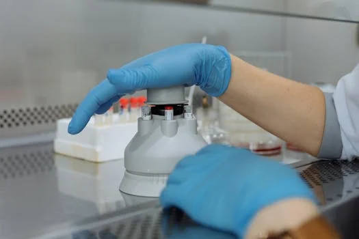
A standard ZLD setup for an IC fab includes the chemical reaction system, adsorption units, high-pressure RO membranes, and a thermal evaporator or crystallizer for the final brine concentration. For a fab processing 150 m³/day, the total CAPEX typically ranges from $1.8M to $2.5M. The primary cost drivers are the evaporation unit and the high-grade stainless steel or plastic-lined piping required to handle corrosive HF-laden influent. Procurement teams should consult a detailed cost analysis for HF wastewater treatment systems to benchmark these figures against regional vendor quotes.
Operating expenses (OPEX) are dominated by chemical consumption and energy. Lime and calcium chloride costs range from $0.50 to $1.50 per cubic meter of treated water. Energy consumption for the RO and evaporation stages adds another $0.20 to $0.80/m³. However, the ROI is realized through three channels: freshwater savings, sludge recovery, and penalty avoidance. In many industrial zones, freshwater costs $1.50–$3.00/m³, and discharge fees are rising. high-purity CaF₂ sludge can sometimes be sold for flux in the steel industry or for cement manufacturing, turning a waste stream into a minor revenue source. A real-world case study of a Shanghai-based fab demonstrated a 3.2-year payback period for a 150 m³/day system by achieving 90% water reuse and eliminating $450,000 in annual discharge fees.
| System Component | CAPEX (50 m³/day) | CAPEX (200 m³/day) | Annual OPEX (Avg) |
|---|---|---|---|
| Precipitation & Clarification | $300,000 | $800,000 | $25,000–$45,000 |
| Adsorption Columns | $200,000 | $500,000 | $15,000–$30,000 |
| RO/NF Membrane Units | $500,000 | $1,200,000 | $40,000–$90,000 |
| Evaporation/Crystallization | $200,000 | $1,000,000 | $60,000–$150,000 |
| Total System | $1,200,000 | $3,500,000 | $140,000–$315,000 |
The ROI can be calculated using the formula: Payback Period = (Total CAPEX) / (Annual Water Savings + Annual Penalty Avoidance - Annual OPEX). For most Tier-1 semiconductor manufacturers, a payback period under 4 years is considered an "automatic buy" for EHS infrastructure projects.
Compliance Checklist: Meeting China GB and US EPA Fluoride Limits
EHS managers must navigate a complex landscape of overlapping regulations.A robust compliance strategy requires more than just a treatment system; it necessitates a rigorous monitoring and maintenance protocol. This includes the installation of online fluoride analyzers with an accuracy of ±0.1 mg/L, situated both after the clarifier and at the final discharge point. These sensors must be calibrated weekly using standard solutions to prevent drift, which is a common cause of regulatory "false positives."
Typical compliance gaps often arise from poor sludge management. If the CaF₂ sludge is not removed efficiently, it can carry over into subsequent stages, fouling membranes and increasing effluent fluoride levels. Implementing high-efficiency sludge dewatering for fluoride precipitation byproducts ensures that the solids are captured and the filtrate is returned to the head of the plant. Additionally, for fabs handling complex chemistries, a pre-treatment with DAF may be necessary to remove oils and CMP surfactants that interfere with the precipitation of fluoride ions. For more comprehensive fab management, refer to our guide on acid-alkaline wastewater treatment for IC fabs.
| Compliance Requirement | China GB 8978-1996 | US EPA 40 CFR 469 | Monitoring Protocol |
|---|---|---|---|
| Fluoride Daily Max | 10 mg/L | 4.0 mg/L | Online analyzer + Daily composite |
pH
Get a Free Quote — Tell Us About Your Project
Contact Us
|