Common DAF Machine Failures and Immediate Signs
An industrial daf machine troubleshooting guide starts with the measured symptom, not a random valve adjustment. A sudden drop in grease removal efficiency below 90% is an immediate warning that air release, coagulation, hydraulics, or mechanical removal needs inspection. Record influent flow, pH, temperature, TSS, oil and grease, pressure, and chemical rates before changing a setpoint.
- Low grease removal rate: A weak or invisible microbubble cloud usually points to a dissolved-air system fault, a blocked releaser, insufficient recycle pressure, or an unsuitable air-to-solids ratio. The contact zone should show a distinct, milky cloud of bubbles rather than clear water. Check the observation port before opening the saturator.
- Unstable or absent scum layer: An imbalance in coagulation, flocculation, hydraulic loading, or the air-to-solids ratio produces thin, patchy scum that the skimmer cannot capture. A healthy scum layer is stable enough to move as a sheet, yet not so thick that the skimmer stalls. FOG means fats, oils, and grease.
- No air-saturated water discharge: Verify that the pressure differential between recirculated water and compressed air exceeds 3.5 kg/cm². A missing differential means the saturator is not delivering microbubbles. Inspect the air control valve, nozzle, compressed-air supply, isolation valves, and pressure gauges in that order.
- Frequent tripping of the DAF pump motor: Blocked release valves, excessive back-pressure, a restricted suction line, wrong rotation, or a failing starter contactor can raise motor current above its protection setting. A trip is a protective signal; repeated resets can damage the motor and hide the original restriction.
Most plants we size for variable industrial loads run near the lower end of their design range during normal production. A symptom log therefore needs both an absolute reading and the preceding stable reading. The change between those readings often identifies the fault faster than a single laboratory result.
Industrial DAF Machine Troubleshooting Guide: 7 Critical Fixes
Industrial DAF troubleshooting follows a fixed order: confirm hydraulics, confirm air release, verify chemistry, inspect flotation, and then test drives and controls. The seven checks below isolate the most common field faults while preserving the original operating envelope and measurement points. A DAF should be adjusted only after the affected variable has been measured.
Step-by-Step Diagnostic Process for DAF Systems
A step-by-step DAF diagnostic process begins by verifying that the recirculation pump generates 3.5–5.0 kg/cm² back pressure. This sequence separates a process upset from a blocked line or failed component. Take readings at steady flow, because a gauge value during pump start-up can be misleading.
- Confirm that the recirculation pump is running and that the pump outlet gauge reads between 3.5 and 5.0 kg/cm², typical for the DAF. A lower value suggests worn impellers, suction restriction, open bypass flow, or inadequate speed. A higher value suggests a blocked releaser, closed isolation valve, or excessive downstream resistance.
- Check the compressed-air gauge. Both gauges must exceed 3.5 kg/cm² and show a clear differential of ≥0.5 kg/cm², indicating that air is being forced into the water stream. If the differential disappears, inspect compressor capacity, air-line restrictions, check valves, and the air control loop.
- Inspect each air-saturated water releaser for blockage or a closed isolation valve. Clean fouling and verify that the release valve is fully open. Mineral scale and biological growth reduce the pressure drop needed for microbubble formation, so inspect the nozzle pattern after cleaning.
- Measure the PAC dose rate with a portable flow meter. The target is 10–50 mg/L for most industrial wastewaters, but the final setpoint must follow jar testing and the actual influent. Compare the measured rate with the controller setpoint to identify calibration drift or diaphragm failure.
- Validate polymer dosing. Over-dosing above 0.5 mg/L PAM can create sticky scum, while under-dosing below 0.1 mg/L produces weak flocs. Adjust the PLC-controlled coagulant and polymer dosing system only after checking dilution water, aging time, suction, and stroke calibration: PLC-controlled coagulant and polymer dosing system.
- Observe scum thickness with a calibrated ruler. A healthy scum layer should be 5–15 mm under normal load. Consistently thin scum indicates weak floc formation or insufficient air; excessively thick, heavy scum can overload the skimmer mechanism.
- If all checks are within specification and performance remains poor, compare a fresh jar test with an influent sample and review the detailed guide to solve polymer dosing issues that impact DAF scum formation.
Use a one-variable change log. Record the old setting, new setting, sample time, flow, pH, temperature, and visual result. This makes a reversible trial distinguishable from a permanent process change and prevents operators from chasing several interacting variables at once.
Critical Pressure and Flow Parameters for DAF Operation
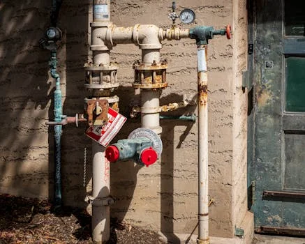
Critical DAF pressure and flow parameters must be read together because a flow change alters pump head, residence time, and bubble release. The original DAF operating benchmark is 3.5–5.0 kg/cm² back pressure. According to the US EPA technical development document for meat and poultry wastewater, DAF saturation is commonly described at 40 to 50 psi (250 to 300 kPa), with 15 to 120 percent recycle in larger units. Those sector reference values do not replace the equipment-specific setpoints below.
| Parameter | Target Range | Measurement Point |
|---|---|---|
| Back pressure (recirculation pump) | 3.5–5.0 kg/cm² | Pump outlet gauge |
| Recirculation flow rate | 20–30 % of influent flow | Flow meter on recirculation line |
| Air-to-solids ratio | 0.01–0.03 m³ air/kg TSS | Calculated from air compressor output and influent TSS |
| Release valve differential pressure | ≥1.5 kg/cm² | Between saturator and flotation tank gauges |
| Influent pH | 6.5–7.5 | Inline pH sensor upstream of coagulant dosing |
Use the table as a diagnostic map rather than a universal design guarantee. If pressure is normal but the contact zone has no whitewater, inspect the release assembly and air control path. If whitewater is strong but clarified water worsens, check solids loading, chemistry, retention time, and skimmer timing.
daf unit low grease removal rate troubleshooting
Low grease removal rate troubleshooting starts with the air cloud and the grease load, because a DAF cannot float material that has not been destabilized or contacted by bubbles. A measured removal rate below 90% is a trigger for investigation, not proof that the pump alone has failed.
- Compare influent and effluent oil and grease results from the same sampling period. A production change can raise the load while the DAF remains mechanically stable.
- Check the observation port for a continuous microbubble cloud. Clear water in the contact zone indicates loss of air dissolution, a blocked releaser, or a pressure-control fault.
- Confirm the recirculation flow is 20–30 % of influent flow and the air-to-solids ratio remains 0.01–0.03 m³ air/kg TSS. Recalculate TSS when the influent changes.
- Inspect scum capture. A stable floating layer can still leave grease in the effluent when the skimmer flight speed, overflow weir, or sludge draw-off is wrong.
The question “why does wastewater from my daf unit at time look milky yellow and at times transparent yellow during operation” usually requires a timed comparison of feed chemistry, bubble density, and skimmer discharge. Milky yellow water can contain dispersed grease, pin floc, or entrained bubbles; transparent yellow water can reflect dissolved color or a different production batch. Sample influent, contact-zone water, clarified effluent, and scum together instead of judging color alone.
According to the EPA document, chemical addition can materially improve oil and grease removal compared with operation without chemical addition, but the cited range is sector-specific. Use plant data and jar tests to determine whether the limiting step is destabilization, floc strength, air supply, or solids capture.
Chemical Dosing Issues That Break DAF Performance
DAF chemical dosing controls particle destabilization and floc strength, so under-dosing polyaluminum chloride below 10 mg/L can reduce grease removal to under 70%. Wastewater characteristics change with product, shift, cleaning water, temperature, and equalization, making periodic jar testing necessary.
- Low coagulant dose: When PAC falls below 10 mg/L, colloids can remain charged and resist floc formation. Increase the dose in 5 mg/L increments while monitoring turbidity, oil and grease, and floc size. Do not make several dose changes before the sample has mixed through the process.
- Incorrect pH: pH outside 6.5–7.5 reduces PAC hydrolysis efficiency. Use an inline pH sensor linked to the dosing controller and maintain the setpoint at 7.0 ± 0.2 where jar tests support it. Sudden influent shifts may require caustic soda or acid feed before coagulation.
- Polymer overdosing: Dosing PAM above 0.5 mg/L can create a gelatinous matrix that adheres to skimmer blades and reduces scum lift. Reduce the polymer feed to 0.2–0.4 mg/L and re-evaluate scum integrity. Large water-filled flocs also increase sludge volume.
- Polymer underdosing: Below 0.1 mg/L, flocs may be too fragile to rise and will disperse through the flotation tank. Match the flow-proportional pump to influent load, and confirm that the polymer is properly aged and mixed before injection.
For precise calibration, integrate the PLC-controlled coagulant and polymer dosing system with SCADA, while retaining a manual verification point. Automated feedback should correct a measured deviation, not amplify a faulty pH probe or flow signal.
daf polymer dosing pam optimization
DAF polymer dosing PAM optimization depends on polymer type, activation, mixing energy, contact time, and wastewater charge demand rather than a fixed dose alone. The original operating guide uses above 0.5 mg/L as an overdosing warning, below 0.1 mg/L as an underdosing warning, and 0.2–0.4 mg/L as a practical reset range for evaluation.
- Prepare the polymer at the approved plant concentration and verify aging time before testing. A dry-feed or make-down error can look like a pump problem.
- Run a controlled jar test across the existing dose, 0.2 mg/L, 0.3 mg/L, and 0.4 mg/L where those values fit the plant's actual feed. Compare floc size, settling or flotation response, clarified water, and scum release.
- Check injection location and mixing. A good dose injected after the useful contact point cannot repair a poor flocculation sequence.
- Verify pump calibration with a container-and-timer test. Compare actual delivery against the PLC setpoint under the same back pressure used during production.
Operators should also record temperature and shear. Fragile flocs can break at a high-shear pump or a turbulent valve even when the jar test looks good. Most plants achieve a more stable result by changing one variable, waiting for a representative residence time, and then comparing laboratory and visual evidence.
Mechanical and Electrical Faults in DAF Units
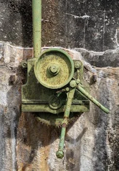
DAF mechanical and electrical faults must be investigated only after the process is placed in a safe state. A unit that stops immediately after start-up may have a self-protection wire fault, high contact resistance, overload, wrong rotation, or hydraulic restriction. Electrical safety precedes any mechanical inspection.
- Immediate shutdown after start: Check the self-protection wire for proper seating and measure starter-contactor resistance; <0.1 Ω is acceptable for the original check. Replace corroded wires and verify overload relays are correctly sized. A momentary voltage spike should be recorded, not assumed.
- Skimmer motor overload: Accumulated solids or misaligned blades increase torque demand. Disassemble the skimmer only under an approved isolation procedure, clear debris, and verify blade parallelism within 0.2 mm. Grinding or straining noises are useful early warnings.
- Clogged nozzles and pipes: High-FOD streams can deposit fats on nozzle tips. Perform weekly ultrasonic cleaning or manual scrubbing where the equipment manual permits it. Strainers on the recirculation line can catch large debris before it reaches the saturator.
- Lockout-Tagout (LOTO) procedure: De-energize the DAF power bus, lock isolation switches, and post a tag indicating “Maintenance – DAF”. Verify zero voltage with a handheld tester before opening an enclosure, and release stored hydraulic or pneumatic energy.
The current eCFR text for 29 CFR 1910.147 requires an energy-control program for servicing where unexpected energization or stored energy could cause injury. It also requires verification of isolation before work begins. The plant procedure must account for electrical, mechanical, hydraulic, pneumatic, chemical, and thermal energy sources.
daf pump motor tripping causes and fixes
DAF pump motor tripping causes and fixes begin with a safe current reading and a hydraulic inspection, not repeated resets. Record the trip time, motor current on each phase, suction pressure, discharge pressure, valve position, and whether the pump was hot or cold.
- Blocked discharge or releaser: A closed valve or fouled nozzle increases head and current. Isolate the pump, depressurize the line, and inspect the releaser path.
- Restricted suction: A dirty strainer, low liquid level, air leak, or collapsed flexible section can cause cavitation and unstable current. Listen for gravel-like noise and compare suction conditions with the commissioning record.
- Electrical overload: Incorrect overload settings, phase imbalance, loose terminals, low voltage, or a failing contactor can trip the motor without a process blockage. A qualified electrician should test energized circuits.
- Mechanical drag: Worn bearings, seal failure, or an impeller rubbing the casing raises current. Do not continue operation when vibration, leakage, or temperature is increasing.
After the cause is corrected, confirm normal current at steady flow and then observe the pump through a complete operating cycle. A single successful restart is not evidence of a durable repair.
daf preventive maintenance schedule continuous run plant
DAF preventive maintenance schedule continuous run plant planning should combine daily observations with weekly, monthly, and quarterly tasks. A disciplined cadence can keep DAF availability above 95% in continuous-run plants when the schedule is matched to loading, fouling, and manufacturer limits.
| Interval | Task | Key Check |
|---|---|---|
| Daily | Inspect pressure gauges, scum thickness, and skimmer operation | Back pressure 3.5–5.0 kg/cm²; scum 5–15 mm |
| Weekly | Clean air-saturated water releasers; verify dosing pump output | Nozzle flow ≥90 % of design; PAC dose 10–50 mg/L |
| Monthly | Check back-pressure settings; inspect recirculation pump seals | Seal leakage <0.2 L/h; pressure stable |
| Quarterly | Full system drain and descaling of saturator tank | Scale deposit <0.5 mm; tank interior visual inspection |
Continuous-run plants should add a trend review to the schedule. Compare the last seven days of pressure, current, PAC, PAM, pH, flow, scum thickness, and effluent quality. A slow drift is often easier to correct during planned maintenance than after a trip or a visible effluent failure.
How to choose a DAF troubleshooting response
DAF troubleshooting response selection should follow the measured fault class. Use the following short checklist before changing equipment or chemical settings.
- Confirm the sample represents the current production load and record flow, pH, temperature, TSS, oil and grease, and operating hours.
- Confirm pressure, differential pressure, recycle flow, and air cloud before changing PAC or PAM.
- Check whether the scum is absent, thin, sticky, excessively thick, or being lost at the skimmer.
- Compare actual chemical delivery with the controller setpoint and verify dilution, aging, suction, and injection location.
- Separate a process fault from a motor, valve, nozzle, contactor, sensor, or PLC fault.
- Document the change and retain the pre-change reading so the result can be reversed.
The Dissolved Air Flotation (DAF) System is the relevant equipment reference for capacity, configuration, and technical data. For a project-specific selection, provide flow, peak flow, temperature, TSS, oil and grease, pH, discharge target, operating hours, and available footprint in one inquiry: request a DAF process review.
Operators who need a second troubleshooting sequence can compare the sibling article DAF Unit for Wastewater Troubleshooting: 7 Data-Backed Fixes. Keep the two records separate when the symptoms, samples, or equipment model differ.
Frequently Asked Questions
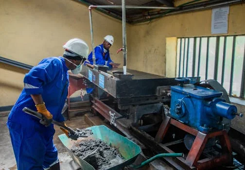
DAF cleaning intervals depend on solids, grease, production hours, and fouling rate; the original mid-size reference is every three months under normal load.
How often should a DAF be drained and cleaned?
A DAF should be drained and cleaned every 3 months for standard loads, with more frequent cleaning for high-fat streams. Increase the interval to monthly when fouling is persistent, and inspect high-loading components weekly in poultry or dairy processing plants. Use pressure, scum, nozzle flow, and pump current trends to confirm whether the interval is adequate.
What pressure should a DAF recirculation pump run at?
A DAF recirculation pump should run at 3.5–5.0 kg/cm² for the operating envelope described here. The gauge must be interpreted with the air differential, recycle flow, releaser condition, and actual whitewater formation. Operating consistently below this range can produce larger, less effective bubbles, but raising pressure without checking valves and nozzles can create a new restriction.
Why is my DAF not forming scum?
A DAF may fail to form scum because coagulant dose is low, pH is outside 6.5–7.5, the air-to-solids ratio is below 0.01 m³ air/kg TSS, or the skimmer cannot capture the floated layer. Check whitewater first, then run a jar test and inspect scum movement. Weak flocs, insufficient air, and poor skimmer timing require different fixes.
How much does a DAF system cost?
A mid-size unit at approximately ≈50 m³/h is described in the original article as starting around US $85,000 with a full chemical integration package. That figure is a retained background estimate, not a current quotation. Final cost depends on construction materials, automation, chemical scope, civil work, freight, installation, and site-specific influent requirements.
How does a DAF work in wastewater?
A DAF dissolves compressed air into recirculated water, releases microbubbles, attaches those bubbles to suspended solids and FOG, and skims the resulting float. Clarified water is withdrawn from the tank for further treatment or discharge. Stable operation depends on pressure release, floc formation, hydraulic loading, and timely solids removal.
Why does wastewater from my daf unit at time look milky yellow and at times transparent yellow during operation?
Milky yellow and transparent yellow DAF water usually reflect different combinations of dispersed grease, pin floc, entrained bubbles, and dissolved color. Compare synchronized influent, contact-zone, clarified-effluent, and scum samples while logging flow, pH, PAC, PAM, pressure, and production batch. Color alone cannot identify whether the primary fault is chemistry, air release, or upstream loading.