A flocculant dosing unit is an automated system that prepares and injects flocculant chemicals such as polyaluminum chloride (PAC) or polyacrylamide (PAM) into wastewater, aggregating suspended particles into larger flocs for easier separation. Modern PLC-controlled units with VSD-driven augers and optical sensors reach ±2% dosing accuracy, which can cut flocculant consumption by up to 30% compared to manual systems. Standard flow rates span 0.1–500 L/h, with solution strengths of 0.1–0.5% for dry polymers and 5–15% for liquid coagulants.
Why Flocculant Dosing Units Matter in Wastewater Treatment
Automated flocculant dosing units cut flocculant use by 20–40% and lift TSS removal to 90–98%, lowering OPEX and stabilizing effluent against NPDES limits. Under 40 CFR 133.102, secondary treatment requires a 30-day average TSS not exceeding 30 mg/L (EPA). Plants above 50 m³/h that replace manual dosing typically recover CAPEX in 12–24 months.
In one textile facility processing 1,500 m³/day, switching to an automated HydropureWater automatic chemical dosing system reduced flocculant costs by 28% and dropped effluent TSS from 120 mg/L to under 15 mg/L (HydropureWater field data, 2025). Inconsistent manual dosing typically pushes consumption to 1.2–1.5× the theoretical dose and risks effluent TSS above 30 mg/L, a common NPDES violation trigger. Automated control therefore protects compliance, cuts sludge volume, and stabilizes treatment performance.
Flocculant Dosing Unit Components: Engineering Specifications
Engineers specifying a new flocculant dosing unit should evaluate six subsystems. Each subsystem controls polymer quality, dosing accuracy, and lifecycle cost.
- Dry-Polymer Feeder: Screw auger systems in 304/316 stainless steel deliver 0.5–50 kg/h with ±1% accuracy. Eductor-blower configurations support pneumatic transfer over longer distances.
- Wetting Head: Jet mixers with 2–4 mm nozzles use 2–6 bar water pressure to disperse powder and prevent "fish-eyes" or undissolved clumps.
- Mixing and Maturing Tanks: Tanks in 304/316 stainless steel or HDPE range from 50 L for batch units to 5,000 L for high-flow service. Propeller mixers at 100–300 RPM handle initial high-shear dissolution; turbine mixers at 50–150 RPM mature the solution over 30–60 minutes for high-molecular-weight PAM.
- Dosing Pumps: Mono pumps with stainless rotors and nitrile stators handle viscous solutions at 0.1–500 L/h. Peristaltic pumps minimize shear degradation of long-chain polymers.
- Control Systems: PLC + HMI with VSD speed control from 0–100%, optical sensors measuring floc settling at 0–100 mm/s, and integration with flow meters and level switches for closed-loop feedback.
- Optional Components: Jacketed or immersion-heated tanks for cold-climate viscosity control, compressed air systems for pneumatic valves, and booster pumps for long dosing lines or high-pressure injection.
| Component | Material/Type | Typical Specification Range | Function |
|---|---|---|---|
| Dry-Polymer Feeder | Screw auger (SS 304/316) | Feed Rate: 0.5–50 kg/h; Accuracy: ±1% | Delivers precise amount of dry flocculant powder. |
| Wetting Head | Jet mixer (SS 304/316) | Nozzle Diameter: 2–4 mm; Water Pressure: 2–6 bar | Rapidly disperses polymer to prevent "fish-eyes". |
| Mixing Tanks | SS 304/316 or HDPE; Propeller mixer | Volume: 50–5,000 L; Mixer RPM: 100–300 | Initial high-shear mixing and dissolution. |
| Maturing Tanks | SS 304/316 or HDPE; Turbine mixer | Volume: 50–5,000 L; Mixer RPM: 50–150; Residence Time: 30–60 min | Ensures full hydration and activation of polymer. |
| Dosing Pumps | Mono pump (SS rotor, Nitrile stator) / Peristaltic | Flow Rate: 0.1–500 L/h; Accuracy: ±2% | Injects prepared flocculant solution into process. |
| Control System | PLC, HMI, VSD | VSD Adjustment: 0–100%; Optical Sensor Range: 0–100 mm/s | Automates operation, monitors, and adjusts dosing. |
How Flocculant Dosing Units Work: Step-by-Step Process
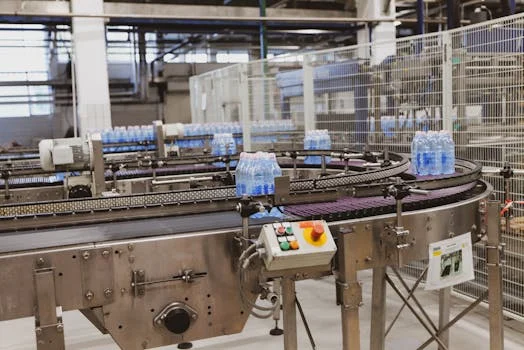
A flocculant preparation system follows six stages that together determine floc quality, dosing consistency, and downstream separation efficiency.
- Step 1: Dry Flocculant Feeding. A VSD-driven screw auger draws powder from a storage hopper, with low-level alarms prompting refill. Localized dust extraction keeps airborne particulate under control.
- Step 2: Wetting and Pre-mixing. The polymer drops into a wetting head where a 2–6 bar jet mixer disperses it in dilution water at a 100:1 to 1,000:1 water-to-polymer ratio, eliminating "fish-eyes."
- Step 3: Hydration and Mixing. A propeller mixer running at 100–300 RPM hydrates the slurry in the dissolution tank, targeting 100–500 cP viscosity.
- Step 4: Maturation. A turbine mixer at 50–150 RPM in the maturation tank provides 30–60 minutes of residence time for PAM (shorter for PAC), allowing full polymer uncoil without excessive shear.
- Step 5: Dosing. A mono or peristaltic pump injects the matured solution just upstream of a flocculation tank or static mixer. Precise chemical dosing pump calibration protects against premature floc shearing.
- Step 6: Feedback Control. Optical sensors measuring floc settling at 0–100 mm/s feed the PLC, which adjusts the VSD to hold target dose and trigger alarms for under- or over-dosing.
Manual vs. Automated Flocculant Dosing: Costs, Efficiency, and ROI
Manual and automated flocculant dosing systems diverge sharply in CAPEX, OPEX, and consistency, and that gap directly sets a plant's payback period. A manual setup, built around a basic dosing pump and hand-mixed polymer, typically costs ¥50,000–¥150,000 in CAPEX and consumes 1.2–1.5× the theoretical flocculant dose while demanding 2–4 hours of operator labor per day.
An automated Automatic Chemical Dosing System with a dry-polymer feeder, multiple tanks, PLC control, and optical feedback runs ¥200,000–¥800,000 in CAPEX but brings flocculant use to 0.9–1.1× theoretical, cuts labor to about 0.5 hours per day, and lifts TSS removal from 85–92% to 95–98%. Floc size consistency improves from ±20% variability to ±5%, which directly stabilizes downstream dissolved air flotation (DAF) systems. For plants above 50 m³/h, payback typically falls between 12 and 24 months; for example, saving 25% on flocculant (¥100,000/year) plus three daily labor hours (¥50,000/year) recovers a ¥300,000 CAPEX in two years. Manual dosing remains viable only for very small plants under 10 m³/h or batch processes with stable influent. Detailed polymer selection criteria are covered in our guide on Polymer Dosing System Specifications: 2025 Engineering Data, Standards & Selection Guide.
| Feature | Manual Dosing System | Automated Dosing System |
|---|---|---|
| CAPEX (Equipment & Install) | ¥50,000–¥150,000 | ¥200,000–¥800,000 |
| Flocculant Consumption | 1.2–1.5× theoretical dose | 0.9–1.1× theoretical dose |
| Labor Costs | 2–4 hrs/day | 0.5 hrs/day |
| TSS Removal Rate | 85–92% | 95–98% |
| Floc Size Consistency | ±20% variability | ±5% variability |
| Payback Period | N/A (continuous OPEX) | 12–24 months (for >50 m³/h plants) |
| Best For | Small plants, batch processes, stable influent | Large-scale, variable influent, 24/7 operation |
Optimizing Flocculant Dosing: Strategies to Reduce Costs and Improve Performance
Optimization hinges on jar testing, influent monitoring, hybrid control, and disciplined maintenance, applied together rather than in isolation.
- Dose Optimization: Daily or weekly jar tests on representative wastewater identify the dose that produces robust, fast-settling flocs and clear supernatant, avoiding both under- and overdosing.
- Influent Monitoring: Continuous TSS, pH (6–8 for PAM, 5–7 for PAC), temperature, and conductivity data let the control logic on a PAC dosing unit or PAM dosing system adjust dose proactively before upset conditions reach the clarifier.
- Control Strategies: Feed-forward control uses influent flow and TSS to predict dose, while feedback control uses downstream optical sensors to fine-tune it. A hybrid loop combining both is the most stable configuration.
- Flocculant Selection: Choose PAC (50–500 mg/L), PAM (1–50 mg/L), or polyferric sulfate based on cost per kg, target dose, floc strength, and the dewaterability of the resulting sludge. Many plants dose a coagulant first, followed by a flocculant.
- Maintenance Best Practices: Calibrate dosing pumps monthly, inspect the flocculant mixing tank quarterly, and clean optical sensors weekly to prevent fouling and dose drift.
- Advanced Techniques: AI-based dosing prediction is gaining traction, using historical data and real-time influent parameters to forecast optimal doses. The same logic applies when integrating these units with DAF clarifiers, as detailed in Dissolved Air Flotation System for Food Processing: 2025 Engineering Specs, Costs & Compliance Guide.
Troubleshooting Common Flocculant Dosing Unit Problems
Most field failures on a flocculant dosing unit come from one of five recurring root causes, and each has a targeted fix.
- Problem: Inconsistent floc formation.
- Causes: Poor mixing in preparation tanks, incorrect flocculant dose, or sudden swings in influent TSS or pH.
- Solutions: Verify mixer RPMs in dissolution and maturation tanks fall inside spec, recalibrate the dosing pump, and add continuous influent TSS and pH monitoring to anticipate dose changes.
- Problem: Pump clogging.
- Causes: Undissolved "fish-eyes" from poor wetting, debris in the feed line, or polymer aging into sticky clumps.
- Solutions: Confirm wetting-head water pressure is adequate, fit a 100-mesh strainer on the pump suction, extend maturation time for full dissolution, and switch to peristaltic pumps for shear-sensitive polymers.
- Problem: Optical sensor errors.
- Causes: Lens fouling from flocs or biological growth, sensor misalignment, or air bubbles crossing the light path.
- Solutions: Clean the lens weekly, recalibrate per manufacturer data, and install bubble traps or correct flow geometry around the sensor.
- Problem: High flocculant consumption.
- Causes: Overdosing, unaddressed influent changes, or poor floc quality that triggers re-dosing.
- Solutions: Re-run jar tests to reset the optimum, update PLC setpoints from the new results, and audit the optical-sensor feedback loop for over-compensation.
- Problem: Low floc settling rate.
- Causes: Under-dosing, wrong flocculant chemistry for the wastewater, or excessive turbulence shearing formed flocs.
- Solutions: Step up the dose gradually and observe settling, switch to a different molecular weight or charge density if needed, and reduce mixer speed or improve baffling in the flocculation tank.
Plant managers sizing a flocculant preparation and dosing system should match pump capacity to dose and flow, verify maturation time for the polymer grade, and confirm closed-loop feedback before purchase.
Frequently Asked Questions
What is the difference between a flocculant and a coagulant?
Coagulants (PAC, ferric chloride) neutralize the negative surface charge on suspended particles so they destabilize and clump into microflocs. Flocculants (PAM) are long-chain polymers that bridge those microflocs into larger, heavier aggregates that settle readily. Most plants dose a coagulant first, then a flocculant, to combine charge neutralization with bridging for the fastest settling.
How do I size a flocculant dosing unit for my plant?
Use the formula Q = (C × F × D) / (S × 1,000,000), where Q is dosing pump flow in L/h, C is flocculant dose in mg/L, F is plant flow in m³/h, D is solution density in kg/L (≈1 kg/L for dilute solutions), and S is solution concentration as a decimal. For 100 m³/h, a 5 mg/L dose, and a 0.2% solution, Q = (5 × 100 × 1) / (0.002 × 1,000,000) = 2.5 L/h, so select a pump rated above 2.5 L/h.
What are the signs of flocculant overdosing?
Overdosed systems show very small, dispersed flocs, high effluent turbidity, foaming in clarifiers, and sludge that is gelatinous and hard to dewater. Reduce the dose step by step using jar-test results and recalibrate the dosing pump or PLC setpoints so the system returns to the target settling rate.
Can I use a flocculant dosing unit for drinking water treatment?
Yes, but coagulants and flocculants must carry NSF/ANSI/CAN 60 certification for drinking water treatment chemicals. Designs typically add higher-grade materials, enhanced disinfection, and stricter monitoring to protect public health.
How often should I replace dosing unit components?
Dosing pumps last 3–5 years (with annual stator, rotor, or tubing replacement), optical sensors 2–3 years, mixers 5–7 years, and SS or HDPE tanks 10+ years. Scheduled inspection and preventive maintenance, rather than reactive replacement, is what keeps accuracy and uptime on target.