An industrial MBR membrane bioreactor couples activated sludge with ultrafiltration membranes, typically 0.05–0.1 μm, so the plant can run MLSS at 8–12 g/L and skip secondary clarifiers. For COD 500–5,000 mg/L, reported COD removal is often 92–97% at flux 15–30 LMH, with footprint about 60% smaller than activated sludge plus tertiary filters. Specs that drive selection are TMP, design flux, scour air rate, and membrane replacement cost of about $20–$50/m²/year under industrial duty.
What defines a fit-for-duty industrial MBR?
A fit-for-duty industrial MBR delivers reuse-grade or strict discharge permeate while holding TMP and energy inside design limits at peak COD and solids load. Typical targets are BOD below 10 mg/L, TSS below 5–15 mg/L, and turbidity below 1 NTU at HRT 4–8 h and MLSS 8–12 g/L. Membrane polymer, flux, and scour air set most of the OPEX.
Why industrial plants adopt MBR systems
Industrial facilities adopt MBR units when land is scarce, discharge limits tighten, or non-potable reuse is planned. A 500 m³/day food processing plant in Minnesota reduced treatment footprint from 200 m² to 80 m² by replacing activated sludge and sand filtration with an MBR (MPCA 2024 compliance data). That scale of land saving matters on urban and brownfield sites.
MBR permeate commonly reaches less than 10 mg/L BOD, less than 15 mg/L TSS, and less than 1 NTU turbidity under stable industrial operation. Those figures are typical membrane bioreactor performance values, not numeric caps inside the U.S. pretreatment rulebook. According to US EPA 40 CFR Part 403 (eCFR current), Part 403 sets pretreatment duties for industrial users discharging to POTWs—pass-through, interference, and prohibited discharges—while categorical concentration limits live in separate subchapter N rules.
Earlier vendor copy often cited EU Industrial Emissions Directive 2010/75/EU as a COD driver for advanced treatment. That directive remains the core EU industrial emissions frame for permits and BAT-based limits. Sector BAT conclusions and local permits still set the numeric COD and nutrient values a plant must meet.
Food and beverage streams often show COD 2,000–8,000 mg/L, TSS 300–1,000 mg/L, and FOG 50–500 mg/L. Pharmaceutical wastewater may reach COD 1,000–10,000 mg/L with variable pH and complex organics. Textile dyeing wastewater typically sits at COD 500–3,000 mg/L with strong color and pH swings. An MBR Membrane Bioreactor Wastewater Treatment System is sized around those profiles after equalization and FOG or toxicity pretreatment.
How submerged MBR trains work: mechanics and key parameters
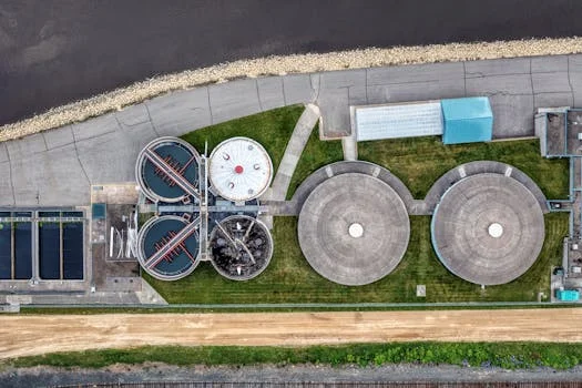
Submerged MBR trains replace the secondary clarifier and tertiary filter with a membrane stage after biological treatment. Mixed liquor is held at MLSS 8–12 g/L and HRT 4–8 hours so biomass can oxidize soluble organics before permeate is drawn through the membrane. Disinfection, if required, follows the permeate pump.
PVDF membranes used in an integrated industrial MBR usually have a 0.1 μm pore size, hydrophilic surfaces, and relatively low biofouling tendency. PTFE membranes commonly span 0.05–0.2 μm, stay hydrophobic, and tolerate aggressive cleaners and solvents. DF Series PVDF flat sheet membrane modules for MBR applications are one submerged flat-sheet option when FOG is moderate and energy is a priority.
Transmembrane pressure (TMP) is the driving force across the membrane. Lower TMP cuts permeate-pump energy and slows cake compaction. Advanced low-resistance designs such as Alfa Laval’s LowResist report TMP of 0.1–0.3 bar, versus conventional industrial MBR TMP of 0.5–0.8 bar. Design flux for industrial MBR duty is typically 15–30 LMH; higher flux shrinks membrane area but raises fouling risk.
Aeration supplies process oxygen and scour air. Membrane scouring commonly uses 0.2–0.5 Nm³/m²/h of air delivered under the modules. Pore blocking and cake layers are the main fouling modes; relaxation and backwash reverse much surface fouling, while irreversible fouling needs chemical clean-in-place.
| Parameter | Typical Industrial MBR Range | Impact on Performance |
|---|---|---|
| MLSS Concentration | 8,000–12,000 mg/L | Higher biomass for pollutant degradation, but increased sludge viscosity. |
| Hydraulic Retention Time (HRT) | 4–8 hours | Longer time for biological reactions, affects system size. |
| Transmembrane Pressure (TMP) | 0.1–0.8 bar | Lower TMP reduces energy, less fouling; higher TMP indicates fouling. |
| Flux Rate | 15–30 LMH | Determines membrane area required; higher flux increases fouling risk. |
| Membrane Scouring Air | 0.2–0.5 Nm³/m²/h | Prevents fouling, but is a significant energy consumer. |
| Dissolved Oxygen (DO) | 1–2 mg/L | Essential for aerobic biological activity. |
PVDF vs PTFE membranes for industrial wastewater
Membrane polymer choice sets chemical cleaning limits, FOG tolerance, and replacement cost. PVDF at 0.1 μm rejects bacteria, viruses, and colloids for most industrial COD loads. PTFE at 0.05–0.2 μm matches that rejection and adds solvent and oxidant tolerance.
PTFE typically withstands pH 1–13 and strong NaOCl cleaning, which suits pharmaceutical and textile dyeing streams. PVDF is generally limited to about pH 2–11. Hydrophilic PVDF resists biofouling; hydrophobic PTFE resists oil and fat adhesion, so high-FOG food plants often specify PTFE after FOG pretreatment.
Energy for PVDF trains is often quoted at 0.3–0.5 kWh/m³ treated water at moderate TMP. PTFE trains more often land at 0.4–0.7 kWh/m³ when TMP runs higher. Service life is commonly 5–8 years for PVDF and 8–10 years for PTFE with disciplined cleaning. Membrane list prices are typically $30–$50/m² for PVDF and $60–$100/m² for PTFE, which dominates long-term OPEX.
| Feature | PVDF Membranes | PTFE Membranes | Key Industrial Application |
|---|---|---|---|
| Pore Size | 0.1 μm | 0.05–0.2 μm | Both: High rejection of bacteria, viruses, colloids. |
| Chemical Resistance | pH 2–11, moderate oxidants | pH 1–13, strong oxidants (e.g., NaOCl) | Pharmaceutical, chemical, textile dyeing (PTFE superior). |
| Fouling Resistance | Good (hydrophilic, resists biofouling) | Excellent (hydrophobic, resists oil/fat fouling) | General industrial (PVDF); Food & Beverage, Petrochemical (PTFE). |
| Energy Consumption | 0.3–0.5 kWh/m³ | 0.4–0.7 kWh/m³ (higher TMP) | PVDF generally more energy-efficient. |
| Membrane Lifespan | 5–8 years | 8–10 years | PTFE often longer due to chemical robustness. |
| Cost (per m² membrane) | $30–$50 | $60–$100 | PVDF lower initial CAPEX, PTFE higher OPEX impact. |
MBR energy consumption: benchmarks and cost controls
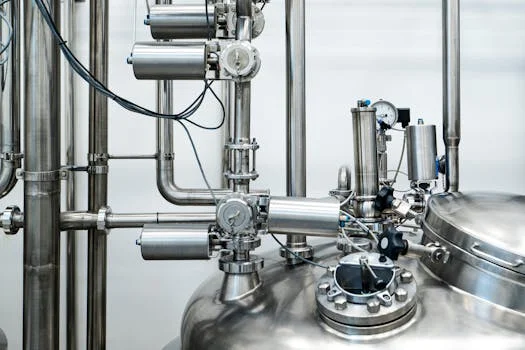
Industrial MBR energy use is usually the largest OPEX line after labor and sludge hauling. Aeration commonly takes 50–70% of power, permeate pumping 20–30%, and sludge recirculation 10–20%. Total specific energy for industrial MBR plants is typically 0.3–0.8 kWh/m³, higher than many municipal MBR trains at 0.1–0.3 kWh/m³ because MLSS and influent strength are higher.
Low-TMP modules cut permeate-pump work. Some low-resistance designs claim TMP near 0.1 bar, versus about 0.5 bar on older submerged stacks, and a few gravity-driven layouts run on roughly 1 m head without a dedicated permeate pump. Holding DO at 1–2 mg/L, fitting VFDs on blowers and pumps, and using short relaxation or backflush cycles all reduce scour and cleaning energy. A textile plant in Barcelona reported a 40% energy cut after moving from a side-stream MBR to a submerged PVDF system with integrated aeration (industry benchmarks).
| Energy Component | Typical % of Total MBR Energy | Industrial MBR Benchmark (kWh/m³) | Cost Reduction Strategy |
|---|---|---|---|
| Aeration | 50–70% | 0.15–0.56 | Optimize DO (1–2 mg/L), efficient blowers, VFDs. |
| Permeate Pumping | 20–30% | 0.06–0.24 | Low TMP membranes, gravity-driven systems, VFDs. |
| Sludge Recirculation | 10–20% | 0.03–0.16 | Optimize recirculation rates, efficient pumps. |
| Chemical Cleaning | Minor (indirect) | Variable | Effective fouling control, optimized cleaning frequency. |
| Total MBR Energy | 100% | 0.3–0.8 kWh/m³ |
What does an industrial membrane bioreactor cost?
Industrial MBR CAPEX typically runs $2,500–$4,000 per m³/day of design capacity, versus $1,500–$2,500 per m³/day for activated sludge with tertiary filtration. The membrane and mechanical package cost more, but civil works shrink because clarifiers and tertiary filters disappear. OPEX is often $0.20–$0.50/m³ for MBR versus $0.15–$0.30/m³ for conventional trains, driven by energy, membrane replacement every 5–10 years, and cleaning chemicals.
Footprint for MBR plants is commonly 0.5–1.0 m² per m³/day, against 1.5–2.5 m² per m³/day for conventional flowsheets—a 50–70% land cut. Effluent from MBR duty is typically BOD below 10 mg/L and turbidity below 1 NTU, while conventional secondary effluent often sits at BOD 20–30 mg/L and turbidity 5–10 NTU before tertiary steps.
A simple payback screen is:
Payback Period = (MBR CAPEX - Conventional CAPEX) / (Annual Conventional OPEX - Annual MBR OPEX + Annual Compliance Penalty Avoidance + Annual Water Reuse Savings)
Use site power price, sludge fees, and reuse credits rather than generic payback claims.
| Feature | MBR Systems | Conventional Activated Sludge + Tertiary |
|---|---|---|
| CAPEX ($/m³/day) | $2,500–$4,000 | $1,500–$2,500 |
| OPEX ($/m³) | $0.20–$0.50 | $0.15–$0.30 |
| Footprint (m²/m³/day) | 0.5–1.0 (50-70% reduction) | 1.5–2.5 |
| BOD Effluent Quality (mg/L) | <10 | 20–30 |
| TSS Effluent Quality (mg/L) | <5 | 10–20 |
| Turbidity (NTU) | <1 | 5–10 |
| Tertiary Filtration Need | Eliminated | Required |
| Sludge Production | Lower (due to longer SRT) | Higher |
How does MBR effluent quality hold under peak flows?
MBR effluent quality stays stable under peak flows when equalization, spare membrane area, and flux setbacks keep TMP inside the design envelope. High solids and COD spikes raise viscosity and cake resistance, so plants that hold net flux near 15–25 LMH during peaks recover faster than units pushed above 30 LMH. Quick recovery usually means short relaxation or backwash, then a return to sustainable flux rather than chemical cleaning on every event.
Design for peaks with 1–4 hours of equalization, a defined peak-to-average flow factor, and membrane area sized on the peak sustainable flux, not only the average day. Keep MLSS from climbing beyond the pump and scour design point during low-flow thick periods. If TMP rises more than about 0.1–0.2 bar above the clean baseline at constant flux, operators should cut flux and check scour air before COD bleed-through appears.
Are flat-sheet MBR membranes backwashable?
Flat-sheet MBR membranes are often cleaned by permeate reverse flow, relaxation, and air scour rather than high-pressure hollow-fiber backwash. Many industrial flat-sheet stacks allow intermittent backflush or reverse permeate pulses at low differential pressure, combined with scour air at 0.2–0.5 Nm³/m²/h. Confirm the supplier’s allowed backwash pressure and chlorine dose; exceeding them shortens PVDF life even if the sheet looks intact.
Backwashable flat-sheet duty still needs periodic maintenance cleans when irreversible fouling accumulates. Plants with sticky FOG or dye residues usually schedule chemical CIP on TMP or permeability triggers, not on a fixed calendar alone.
How to select an MBR membrane bioreactor for your plant
Selecting industrial membrane equipment starts with measured influent data and a written effluent or reuse specification. Dairy wastewater often shows COD 2,000–5,000 mg/L and FOG 500–1,000 mg/L, while pharmaceutical streams can exceed COD 10,000 mg/L with toxic fractions that need pretreatment.
Selection checklist
- Characterize COD, BOD, TSS, FOG, pH, temperature, and peak/average flow.
- Write discharge or reuse limits (local permit, EPA pretreatment program, EU BAT-based permit, or China GB 18918-2002 where applicable).
- Choose PVDF for general industrial loads; choose PTFE for high FOG, extreme pH, or strong oxidants.
- Size HRT at 4–8 hours and membrane area at 15–30 LMH on the governing flow case.
- Estimate energy at 0.3–0.8 kWh/m³ and ask for guaranteed membrane life and replacement price.
- Require equalization and FOG or toxicity pretreatment when peaks or inhibitors are documented.
- Compare lifecycle cost, not only installed CAPEX, before award.
When you shortlist packages, compare an MBR Membrane Bioreactor Wastewater Treatment System against site power cost, sludge disposal, and reuse value. For Minnesota and similar U.S. pretreatment programs, map local limits to 40 CFR Part 403 duties and any categorical rule that applies to your sector.
| Industrial Sector | Typical Influent COD (mg/L) | Typical Influent FOG (mg/L) | Recommended Membrane Type | Key Design Consideration |
|---|---|---|---|---|
| Dairy Processing | 2,000–5,000 | 500–1,000 | PTFE (for high FOG) | Pre-treatment for FOG, robust membrane cleaning. |
| Pharmaceutical | 1,000–10,000+ | <50 | PTFE (for chemical resistance) | High chemical resistance, specialized biological treatment. |
| Textile Dyeing | 500–3,000 | <100 | PVDF or PTFE (for pH/color) | Color removal, pH stability, oxidant resistance. |
| Food Processing (General) | 1,000–8,000 | 100–500 | PVDF (general) or PTFE (high FOG) | Organic load variability, FOG management. |
| Chemical Manufacturing | 1,000–15,000+ | Variable | PTFE (for extreme chemicals) | Chemical compatibility, toxicity, robust pre-treatment. |
Cost drivers that move the bid are membrane area at the peak flux case, blower size for scour air at 0.2–0.5 Nm³/m²/h, chemical cleaning frequency, and sludge haulage after long SRT operation. Ask vendors for TMP and specific energy at your COD and temperature, not only nameplate flux.
Who this is for: plant engineers and EPC teams comparing MBR against CAS plus tertiary filtration on footprint, reuse, or tight BOD/TSS permits. Who should look elsewhere: sites with untreated free FOG above design limits, or wastes that need anaerobic or physicochemical treatment before any aerobic membrane stage. Next step: send flow, COD, FOG, and permit limits with a Request a free quote so membrane area and energy can be checked on your duty cycle.
Frequently Asked Questions
What flux should an industrial MBR use?
Industrial MBR systems typically run at 15–30 LMH depending on wastewater strength, temperature, and membrane polymer. Higher flux reduces installed area but raises TMP and fouling risk, especially above about 30 LMH on high-solids peaks. Sustainable design usually sizes membrane area on the peak day at the lower half of that band.
How does MBR effluent compare with conventional treatment?
MBR permeate typically reaches less than 10 mg/L BOD, less than 5 mg/L TSS, and less than 1 NTU turbidity without a separate tertiary filter. Conventional activated sludge often leaves BOD 20–30 mg/L and TSS 10–20 mg/L before tertiary polishing. That gap is why MBR is chosen when reuse or strict discharge limits apply.
What drives MBR energy use?
Aeration usually consumes 50–70% of MBR power, followed by permeate pumping at 20–30% and sludge recirculation at 10–20%. Industrial plants often land at 0.3–0.8 kWh/m³ treated water. DO control at 1–2 mg/L, VFDs, and low-TMP membranes are the main levers to cut that total.
How long do MBR membranes last and what do they cost?
PVDF membranes typically last 5–8 years at replacement costs of $30–$50/m² under industrial cleaning regimes. PTFE membranes often last 8–10 years but cost $60–$100/m² to replace. Cleaning frequency, oxidant dose, and FOG control change those ranges more than brand claims alone.
Can an MBR treat high-strength industrial wastewater?
Yes, MBR trains treat high-strength industrial wastewater in the COD 500–5,000 mg/L band, and higher with proper pretreatment. High MLSS at 8–12 g/L and HRT of 4–8 hours support that load if inhibitors and FOG are controlled upstream. Equalization is required when peaks would push flux or TMP outside the membrane warranty window.