How the cavitation air flotation process flow works
The cavitation air flotation process flow normally runs from wastewater collection and equalization through optional screening or oil-water separation, chemical conditioning, cavitation and microbubble generation, flotation clarification, and sludge withdrawal, ending at a clarified-water outlet. CAF introduces air as microbubbles directly into the wastewater rather than first dissolving it in a pressurized saturation vessel. Chemical conditioning destabilizes particles and promotes flocculation, allowing the flocs to attach to bubbles, rise, and be removed by surface skimming. The 2022 Processes study identifies air flotation as a core oily-wastewater treatment technique and notes that Shell introduced it into oilfield produced-water treatment in 1960. Depending on the feed, clarified water may continue to biological treatment, tertiary treatment, reuse, or permitted discharge.
Equalization is more than a buffer tank: it stabilizes flow and pH before dosing, which protects downstream separation equipment from shock loads. Screening or an oil-water separator may be required where rags, debris, free oil, or emulsified oil would interfere with the aerator or chemical system. The condition itself depends on the wastewater. An automatic coagulant and flocculant dosing system should provide separate, adjustable reagent addition and defined mixing or contact stages.
CAF then creates bubbles in direct contact with conditioned wastewater. The bubbles provide flotation surfaces for suspended solids, colloids, oils, and grease, while heavier particles can settle in the same equipment. Floatable material is skimmed from the surface; bottom solids are withdrawn separately. The clarified-water outlet is therefore the start of the next treatment step, not necessarily the final effluent route.
Cavitation air flotation process flow diagram
A complete cavitation air flotation process flow diagram must show the wastewater, chemical, air, solids, and clarified-water streams separately. The basic arrangement is:
Raw wastewater inlet → equalization → optional screening/oil-water separation → conditioning reactor → coagulant and flocculant dosing → cavitation chamber → flotation chamber → surface skimmer → sludge outlet
Air inlet → aeration system → cavitation chamber
Flotation chamber bottom → heavier-solids collection → sludge outlet
Flotation chamber weir → clarified-water outlet → downstream treatment, reuse, or permitted discharge
The air branch is a defining part of the schematic. Ambient or compressed air enters the aeration system and is converted into microbubbles in the cavitation stage. In the CAF arrangement described by IPPTA in September 1995, vacuum produced by a cavitation aerator draws air through a draft tube and promotes a natural recycle of 20–25% of total hydraulic volume from the flotation chamber to the cavitation chamber. That recycle belongs to the cited design; it should not be assumed for every CAF unit.
The solids branch also needs two withdrawal paths. Surface skimming removes floated solids, oils, and grease. Heavier settled solids leave from the bottom. If the flotation residue requires further water removal before disposal, the sludge line should continue to a plate and frame sludge filter press or another site-approved dewatering method.
| Diagram location | Required function | Information to show on the supplier drawing |
|---|---|---|
| Raw wastewater inlet | Receives the design flow and contaminants | Maximum and average flow, flow profile, inlet connection |
| Equalization | Stabilizes flow and pH | Tank duty, mixing arrangement, level measurement |
| Conditioning | Destabilizes particles and forms flocs | Coagulant and flocculant points, mixers, contact zones |
| Cavitation chamber | Generates microbubbles in direct contact with the feed | Aerator type, drive arrangement, suction and discharge details |
| Flotation chamber | Separates attached solids and oil | Retention arrangement, weir, surface skimmer |
| Solids withdrawal | Removes floated sludge and bottom solids | Scraper, beach or beach alternative, auger, sludge outlet |
| Clarified-water outlet | Transfers treated water downstream | Weir, outlet level, turbidity or solids monitoring |
| Controls | Coordinates dosing, aeration, skimming, and sludge removal | Interlocks, alarms, local/remote control and data points |
What happens inside the cavitation and flotation zones
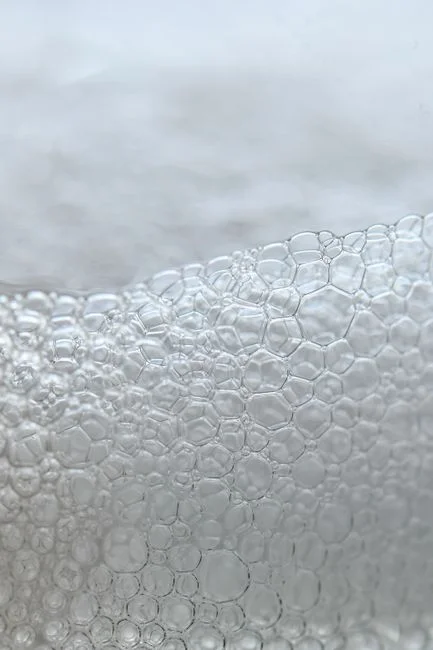
The cavitation zone is where the conditioned wastewater meets the microbubbles; it is not a pressurized air-saturation tank. IPPTA’s September 1995 design uses a hollow four-pronged impeller rotating at 1,700 rpm. It reports that cavitation and shear collapse the introduced air into microbubbles between 500 nm and 1 mm. These values describe that published system and should not be converted into universal design guarantees.
The separation sequence begins when a coagulant destabilizes particles that would otherwise remain dispersed. After adequate contact, a flocculant promotes agglomeration into flocs suitable for flotation. Bubbles then provide the lifting vehicle. Bubble-particle flocs move upward to the surface, where the skimmer removes them from the liquid. Heavier solids that do not float are collected from the bottom.
Retention is design-specific. IPPTA reports 2–4 seconds for floc formation before flotation and 17 minutes in the flotation chamber in the published design. The chemical program, feed composition, hydraulic arrangement, and solids properties determine actual contact and clarification performance; the cited retention figures should be used to interrogate a supplier’s design basis rather than copied into another project specification.
| Mechanism | Published value or condition | Engineering implication |
|---|---|---|
| Cavitation aerator | Hollow four-pronged impeller at 1,700 rpm | Require the exact aerator arrangement, drive data, and maintenance access |
| Reported bubble range | 500 nm to 1 mm | Source-specific; confirm whether the supplier’s stated range covers the operating condition |
| Floc retention | 2–4 seconds | Published-design value; verify conditioning sequence and mixer performance |
| Flotation retention | 17 minutes | Published-design value; check against feed loading and target clarification |
| Natural recycle | 20–25% of total hydraulic volume | Present in the IPPTA design; clarify whether the offered configuration uses the same arrangement |
| Performance dependencies | SS, BOD, COD, and FOG depend on the chemical program and feed composition | Require jar testing or representative-feed confirmation before fixing guarantees |
How each process stage affects separation performance
Equalization, conditioning, bubble generation, flotation, and solids withdrawal form one coupled process, so poor performance often begins before the flotation chamber. IPPTA’s September 1995 paper identifies flow equalization and pH stabilization as pretreatment operations and notes that suspended solids usually contribute 30–70% of wastewater BOD. Efficient solids removal can therefore reduce the load entering biological treatment, although the applicable reduction depends on the wastewater and removal achieved.
Chemical conditioning is the first control point to review when clarification is weak. IPPTA identifies coagulant selection, sufficient contact before flocculant addition, and the correct addition point as central design criteria. Its published system forms flocs almost immediately after suitable flocculant dosing, so poor mixing, incorrect reagent order, variable pH, or excessive shear can undermine bubble attachment before flotation begins.
Inside the flotation zone, adequate bubble distribution and suitable hydraulic conditions are essential. If conditioning is inconsistent or the flotation pattern is poorly maintained, flocs may not rise or may be carried back into the clarified-water outlet. Numerical operating limits require site-specific design data; the supplied research does not establish universal thresholds.
Solids separation must be included in the performance review. The IPPTA design uses scrapers to pull surface sludge over an angled beach into a collection channel and a screw auger for withdrawal. That arrangement is not universal, but the selected skimmer and sludge system must prevent accumulated float from re-entering the treated-water stream.
Monitoring should cover flow, pH, suspended solids, oil and grease, turbidity, and the bulk parameters relevant to the downstream process. A supplier should identify where each measurement is taken and how it triggers a dosing, skimming, or alarm response. For downstream polishing, clarify whether a filtration stage such as a multi-media filter is required.
CAF versus DAF and conventional clarification

CAF, DAF, and settling clarify different process problems, so the comparison should start with the air-generation route and the required separation mechanism. In the cited CAF configurations, microbubbles are generated directly by cavitation; in the IPPTA description of DAF, air is dissolved in water before flotation. A lamella clarifier relies primarily on settling rather than bubble attachment.
| Decision point | CAF | DAF | Conventional or lamella clarification |
|---|---|---|---|
| Air-generation route | Direct microbubble generation through cavitation | Air is dissolved in water before flotation | No bubble-generation stage is required |
| Equipment described by SIGMADAF and IPPTA | Cited configurations do not require air compressors, recirculation pumps, pressurized tanks, or injection nozzles | The IPPTA description identifies air compressors and recirculation pumps | Requires tank and solids-settling equipment |
| Primary separation | Floatation of suspended solids, oils, grease, and colloids; heavier solids may settle separately | Flotation of conditioned solids | Primarily solids settling |
| Typical position | Pretreatment, secondary clarification after biological treatment, or tertiary clarification, according to SIGMADAF | Flotation clarification after physicochemical conditioning | Clarification where settleable solids are the target |
| Main buyer check | Feed chemistry, aerator design, conditioning, hydraulic loading, and skimming | Saturation, recycle, nozzle condition, and hydraulic loading | Settling area, sludge withdrawal, and solids characteristics |
No universal cost, footprint, or removal advantage should be assumed. If the wastewater contains significant floatable oil, grease, or colloids, CAF may warrant direct comparison with DAF. If the main objective is settling and the solids lack useful flotation characteristics, clarification may be more appropriate. Further application-specific assessment is available in compare DAF and clarifiers for fabricated metals wastewater.
How to size and specify a CAF treatment system
A CAF system cannot be sized reliably from a nominal flow alone. Request maximum and average flow, the flow-duration profile, wastewater temperature, pH range, and the required treatment objective. The supplied research provides no universal sizing equation, so the supplier must explain how each selected unit handles peak flow, hydraulic retention, conditioning demand, and solids loading.
The wastewater characterization request should include suspended solids, oil and grease, colloid behavior, COD, and BOD, together with contaminants relevant to the industry. These match the performance indicators discussed by IPPTA. Also request representative samples, existing pretreatment data, discharge or reuse targets, downstream treatment requirements, and the intended sludge-disposal route.
SIGMADAF reports a commercial CAF capacity range of 3–250 m³/h. Use that as a supplier-reported screening reference for initial equipment discussions, not as a project-sizing conclusion. Hydraulic behavior, feed chemistry, operating mode, and treatment targets still have to be resolved for the selected arrangement.
Ask each supplier to define the aeration device, bubble-generation method, conditioning sequence, flotation-retention arrangement, surface-skimming mechanism, sludge collection, recycle arrangement, materials of construction, controls, and available tank dimensions. Require the proposed guarantees to identify the tested feed conditions, treatment objective, equipment scope, and sampling basis.
| Procurement package | Minimum information to request | Why it matters |
|---|---|---|
| Design basis | Peak and average flow, flow profile, temperature, pH range, treatment objective | Defines the hydraulic and process envelope |
| Feed analysis | SS, oil and grease, colloid behavior, COD, BOD, industry-specific contaminants | Controls reagent selection and expected separation |
| Equipment scope | Aerator, conditioning tanks, flotation chamber, skimmer, sludge withdrawal, recycle, materials | Prevents omissions between unit price and installed scope |
| Controls | Instrument list, interlocks, alarms, duty/standby strategy, manual overrides | Connects the flow diagram to operable equipment |
| Performance basis | Feed conditions, analytical method, operating mode, guarantee limits, exclusions | Distinguishes tested performance from generic claims |
| Downstream interfaces | Clarified-water requirements, sludge route, dewatering, utilities, access | Completes the plant boundary and compliance route |
IPPTA reports expected suspended-solids removal above 90% and removal commonly above 95% when the correct chemical program is used. Treat these as source-specific expectations, not guaranteed project results. Confirm them through jar testing, pilot work, or representative-feed testing, and align them with the HydropureWater DAF and flotation systems enquiry as a basis for technical comparison rather than a substitute for site data.
Expected performance and maintenance considerations
Expected CAF performance must be tied to the wastewater and chemical program. IPPTA’s September 1995 publication reports expected suspended-solids removal above 90%, commonly above 95% with the correct chemical program, and typical BOD removal of 40–50%, with COD removal slightly higher. Those figures describe the cited CAF application and should be validated against the project feed.
The published examples show how feed composition changes the result. A tanner wastewater application achieved 97% SS and 96% FOG removal; dairy wastewater achieved 80% SS removal; and textile wastewater achieved 97% SS removal. The associated organic-load reductions also differed, reinforcing that suspended-solids removal alone does not determine BOD or COD performance.
The same IPPTA source reports power requirements of 2 hp for 20 m³/h wastewater and 3 hp for wastewater flows up to 150 m³/h for its described system. These are equipment-specific figures, not universal power calculations. Require the motor rating, aerator drive arrangement, and connected-load definition for the offered equipment.
Maintenance information should cover aerator inspection, skimmer alignment, sludge-discharge checks, control-system maintenance, chemical-line verification, and monitoring of downstream solids accumulation. The solids-handling route should be defined before startup because a reliable skimmer does not complete the treatment train if the resulting sludge has no discharge or dewatering plan.
Frequently Asked Questions
How much does a CAF treatment system cost?
No supported project price is available in the research, so a responsible quotation requires the peak and average wastewater flow, wastewater analysis, treatment targets, available footprint, utilities, required equipment scope, controls, sludge route, and downstream treatment. Request an itemized quotation separating equipment, tanks, aeration drive, chemical dosing, controls, installation, commissioning, and performance testing. Do not compare quotations unless their boundaries and feed assumptions are the same.
Can a supplier size a CAF system from the 3–250 m³/h commercial range?
No. SIGMADAF’s 3–250 m³/h figure is a supplier-reported commercial range, not a universal design rule. Use it to identify candidates, then require the supplier to explain how the unit handles peak flow, hydraulic retention, feed loading, chemistry, operating mode, and clarified-water targets using the actual wastewater data.
How should a CAF supplier be evaluated?
Ask for the tested feed conditions, treatment objectives, equipment boundary, analytical methods, operating mode, performance guarantees, and exclusions behind the proposal. A credible response should also define the cavitation aerator, microbubble-generation method, conditioning sequence, flotation arrangement, surface skimming, sludge collection, recycle, controls, and maintenance access. Generic removal percentages without feed and test conditions are not enough.
What operating evidence should be requested before accepting a CAF proposal?
Request representative-feed testing or pilot data covering suspended solids, oil and grease, turbidity, COD, and BOD, together with the chemical program and operating conditions. The supplier should also provide startup procedures, alarm and interlock lists, critical spares, aerator and skimmer maintenance plans, and the route for both clarified water and removed solids.