Why Pumps Sit at the Center of a Fab Water Loop in 2026
Total water demand at a 300 mm wafer facility can exceed 2,000 gallons per minute, and the way that water is moved — not just treated — determines whether a reuse program actually pays back (Kurita America). Advanced fabs are shifting toward onsite wastewater treatment and reuse, treating water only as clean as the next downstream process needs (Kurita America).
That philosophy changes the role of the pump: it is no longer a commodity line item that pushes liquid from A to B, but the boundary asset that decides which stream a unit of water joins next. Reclaimed process rinse water is already being repurposed as cooling-tower makeup in documented fab programs, which means the pump now sits between the fab utility loop and the treatment skid (Ecolab). Engineers must size a network rather than a single pump: UPW distribution to final rinses, scrubber circulation across CVD, etch and diffusion tools, scrubber blowdown to treatment, and reclaim-to-UPW or cooling-tower makeup. Each of those duties has different chemistry, pressure and purity requirements, and the 2026 design task is to map the right pump class to the right stream. The UPW loop sizing guidelines for semiconductor fabs cover the hydraulic side; this guide covers how pump selection ties into that hydraulic envelope.
The Four Streams a Scrubber and UPW Pump Must Serve
A single pump specification will fail on this loop because the four streams are chemically and hydraulically different. UPW distribution feeds the final rinses that contact the wafer surface, and it is the tightest purity window on the site; commercial systems such as Ecolab Ultra-Pure Water+ already provide online monitoring for contaminants including urea and trihalomethanes, which means any pump on this duty must not contribute leachables, particles or TOC that would blind the analyzer (Ecolab). Scrubber circulation is the liquid that flows through the packed bed or spray nozzle of a gas scrubber to capture acid, ammonia, SiH4 and particulate from tool exhaust; chemistry is aggressive and temperatures can be elevated depending on the tool mix. Scrubber blowdown-to-treatment is the spent liquor sent onward to neutralization, fluoride precipitation, or membrane polishing — this is the duty that industrial RO systems for fab reclaim polishing and UF pretreatment for fab scrubber blowdown and reclaim streams are designed to handle. Reclaim-to-UPW is the polished effluent being sent back toward UPW makeup or to the cooling tower; the same Ecolab program documents reclaimed process rinse water being used as cooling-tower makeup, so the pump hydraulics on this stream must not break that reuse pathway (Ecolab). Treating these as one duty is the most common specification error in 2026 retrofit work.
| Stream | Typical chemistry / load | Key pump-side risk | Downstream interface |
|---|---|---|---|
| UPW distribution | Resistivity-class water, monitored for urea / THM | Leachables, particles, TOC contribution | Final rinse manifolds, polishing loop |
| Scrubber circulation | Acid / NH3 / SiH4 + particulate; elevated T | Corrosion, seal failure, gas locking | Packed bed or spray nozzle |
| Scrubber blowdown → treatment | Fluoride, silica, TSS, metals, varying pH | Solids handling, fluoride attack, precipitation | Neutralization, UF, RO |
| Reclaim → UPW / cooling tower | Polished, low-TOC water; may carry trace ions | Re-introducing ions upstream of EDI; cross-contamination | EDI, cooling-tower makeup |
Pump Classes, Materials and Sealing for Each Stream
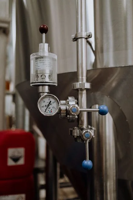
The right pump class, metallurgy and seal configuration depends entirely on which of the four streams the unit is serving. On UPW distribution, the typical choice is a non-metallic or low-leakage centrifugal or magnetic-drive pump with a cleanroom-compatible footprint; the wetted path must not add TOC or particles that would interfere with the online UPW monitoring standard in commercial programs (Ecolab). On scrubber circulation, the wetted materials should be corrosion-resistant alloys or fiber-reinforced plastic matched to the actual tool chemistry — CVD, etch and diffusion tools each produce different scrubber liquor — and a mechanical seal with a documented leakage class that fits both the chemistry and the temperature window. Magnetic-drive pumps are often specified here to eliminate the seal as a leak path, but the engineer must confirm that the bearing materials and containment shell are compatible with the acid or alkaline service. On scrubber blowdown-to-treatment, solids- and fluoride-tolerant pumps with open or vortex impellers are the right starting point because neutralization generates precipitates; lining and seal materials should be cross-checked against the local discharge envelope for fluoride, TSS and metals, which the engineer must obtain from the site's permit file. On reclaim-to-UPW, the pump must be specified for polished, low-TOC water with wetted materials consistent with downstream RO, UF and EDI polishing; the continuous electrodeionization for ultrapure water makeup replaces mixed-bed ion exchange specifically to avoid regeneration waste, and the upstream pump must not reintroduce the ions that EDI is trying to remove. A magnetic-drive pump on this duty is a defensible choice where zero leakage is required, but the engineer still has to validate the containment-shell material against any residual oxidant in the polished stream.
| Stream | Recommended pump class | Material of construction | Sealing / leakage class |
|---|---|---|---|
| UPW distribution | Non-metallic centrifugal or magnetic-drive | PP, PVDF, PTFE-lined, or low-leach alloy | Zero-leakage magnetic drive preferred; verify with online UPW monitoring |
| Scrubber circulation | FRP or alloy centrifugal; magnetic-drive where chemistry permits | Alloy 20, Hastelloy, FRP; bearing materials matched to liquor | Mechanical seal rated for chemistry and T; confirm leakage class against EHS review |
| Scrubber blowdown → treatment | Open-impeller or vortex centrifugal | FRP, rubber-lined, or high-Ni alloy; check against fluoride envelope | Mechanical seal with flushed seal plan; solids-tolerant |
| Reclaim → UPW / cooling tower | Low-leakage centrifugal or magnetic-drive | Low-TOC compatible; ions must not be re-added upstream of EDI | Zero-leakage magnetic drive preferred; monitor for cross-contamination |
Sizing the Scrubber and Reclaim Pumps Against the 2,000 gpm Site Envelope
A 300 mm fab can pull in excess of 2,000 gallons per minute through rinsing, abatement and cooling combined (Kurita America). The engineer should partition that envelope into the four stream categories — UPW rinses, scrubber circulation across all tools, scrubber blowdown to treatment, and reclaim-to-UPW or cooling-tower makeup — using the tool count and abatement device list as the input. The next step is to apply a reclaim ratio consistent with the design intent of treating water just enough for the next process, as Kurita America frames it; the higher the reclaim ratio, the more critical pump specification becomes, because blended water re-enters the cleanest loops and any pump-side contamination shows up directly on wafer or in the cooling tower. Where reclaimed process rinse water is being reused as cooling-tower makeup, at least one pump stream must be capable of handling cooling-tower chemistry in addition to scrubber blowdown chemistry (Ecolab). The final sizing check is pressure duty: UF, RO and EDI each set a feed-pressure window that the selected pump curve must sit within across the expected turndown range, and the UPW system performance criteria and specifications together with the UPW loop sizing guidelines for semiconductor fabs give the hydraulic boundary. Without a tool-level flow breakdown, the engineer should treat the per-stream percentage as an input to be collected from the site's mass balance, not a value to be assumed.
From Reuse Decision to Pump Specification: A 2026 Selection Framework
The defensible ordering for 2026 procurement is to select pump class first, then material of construction, then sealing and leakage class, then controls — this prevents the common failure of over-specifying metallurgy on the wrong pump type. Documented fab programs show why this ordering matters: an NXP–Ecolab program reported an 11.5% air-handler electrical reduction, 1.22 million kWh saved, 900 tons of CO2 avoided and $111,348 in annual savings, and a second program reported 7,000,000 gallons of water saved and 3,369 tons of CO2 avoided per year, both of which depend on integrated pump and treatment decisions rather than a single equipment swap (Ecolab). The pump boundary on the scrubber-to-treatment line and the pump boundary on the reclaim-to-UPW line are different assets with different spares, even if they sit on the same skid. For 2026 acceptance criteria, build the spec around online monitoring compatibility — urea and THM sensing is already deployed in commercial UPW systems (Ecolab) — so that pump wetted materials do not blind the analytical system or show up as false positive excursions. The RO membrane system design criteria for industrial wastewater and the related ion-exchange guide define the polishing-side envelope the pump must feed into. A pump that protects the reuse loop turns these performance outcomes from a one-time program into a repeatable 2026 design pattern.
Frequently Asked Questions
What information do I need to bring to a 2026 supplier conversation for scrubber and UPW pumps?
Bring the tool-level mass balance that partitions the site total — Kurita America cites 2,000 gallons per minute at 300 mm scale — into the four stream categories, plus the actual scrubber chemistry per tool group (CVD, etch, diffusion) and the discharge envelope (fluoride, TSS, metals) from the site's permit. Ask the supplier to confirm wetted-material compatibility against that specific chemistry, to document the seal leakage class, and to show that the pump curve sits within the feed-pressure window of the downstream RO, UF or EDI unit. The defensible check is whether the supplier's proposal ties pump metallurgy and sealing to your stream-by-stream chemistry list, not a generic compatibility chart.
How do I build a defensible cost-and-reuse case for upgrading the pump set in 2026?
Anchor the business case to documented fab outcomes: an 11.5% air-handler electrical reduction, 1.22 million kWh saved, $111,348 annually in one program and 7,000,000 gallons of water saved with 3,369 tons of CO2 avoided per year in another (Ecolab). The engineering input you must obtain from site data is the current reclaim ratio and the per-stream flow split; without those, the CAPEX payback can only be framed qualitatively as "treat just enough for the next process" (Kurita America), not as a numerical ROI.
Can a magnetic-drive pump be used on every stream in the loop?
No. Magnetic-drive pumps are a defensible choice for UPW distribution and reclaim-to-UPW where zero leakage is required and the fluid is clean, but on scrubber circulation the bearing materials and containment shell have to be checked against the actual acid or alkaline chemistry. On scrubber blowdown-to-treatment, the abrasive and precipitating nature of the stream usually calls for an open-impeller or vortex centrifugal with a flushed mechanical seal rather than a magnetic drive. Treat the choice as stream-specific, not as a site-wide standardization decision.
How do I make sure the new pumps do not undermine the online UPW monitoring?
Specify wetted materials that do not add TOC, particles or specific ions that the online analyzer is looking for — commercial UPW