Solvent wastewater treatment by MBR achieves 99% COD removal and under 10 mg/L TSS using PVDF membranes at 12–20 LMH flux, with HRT of 6–12 hours and 0.6–1.2 kWh/m³ energy demand for solvent-duty aeration and scour.
Solvent Wastewater Treatment by MBR: 2027 Performance Baseline
Solvent wastewater treatment by MBR pairs solvent-tolerant biomass with a PVDF membrane barrier, achieving 99% COD removal, TSS below 10 mg/L, and TOC removal above 98% at design fluxes of 12–20 LMH. Footprint runs about 60% smaller than conventional activated sludge for the same load. Energy demand spans 0.6–1.2 kWh/m³ for solvent-duty aeration and scour.
MBR Membrane Bioreactor for Solvent Laden Wastewater: Why CAS Fails
Conventional activated sludge (CAS) systems frequently fail in pharmaceutical and chemical plants because solvents inhibit microbes at concentrations far below typical influent levels. According to the EPA 2024 Toxicity Database, the EC50 for toluene is 12 mg/L, while methanol sits at 2,500 mg/L. When influent holds 300–5,000 mg/L of these compounds, CAS floc undergoes rapid deflocculation.
Polar solvents such as acetone and isopropyl alcohol (IPA) disrupt the extracellular polymeric substances that bind sludge flocs. That disruption drives 30–50% TSS carryover in secondary clarifiers, with permit risk and downstream fouling. Non-polar solvents like xylene and hexane strip into aeration off-gas, which can violate VOC limits under EPA Method 25A and force costly scrubbing.
A paint plant in Jiangsu illustrates the gap. Its CAS train could not handle 1,200 mg/L methyl ethyl ketone (MEK), and effluent COD stayed above 800 mg/L. After switching to a MBR Membrane Bioreactor Wastewater Treatment System with PVDF membranes, COD fell from 8,500 mg/L to <50 mg/L. Solids separation no longer depended on floc settleability.
| Solvent Type | Influent Range (mg/L) | CAS Failure Mechanism | MBR Performance Advantage |
|---|---|---|---|
| Polar (Methanol, IPA) | 1,000–5,000 | Floc disintegration; 40% TSS carryover | Physical barrier ensures <1 mg/L TSS regardless of floc health |
| Non-Polar (Toluene, Xylene) | 50–500 | Microbial toxicity (EC50 <20 mg/L); VOC stripping | High MLSS (10g/L+) increases toxicity resistance; submerged filtration limits stripping |
| Ketones (MEK, Acetone) | 500–2,000 | Sludge bulking; poor sedimentation | Elimination of clarifiers removes sedimentation constraints |
PVDF Membrane for Solvent Wastewater Treatment: Material, Pore Size, and Configuration
Membrane material selection sets service life in solvent-heavy streams, and polyvinylidene fluoride (PVDF) with a 0.1 μm pore size remains the 2027 industry standard for general solvent duty. PVDF resists swelling in methanol and ethanol and holds integrity across pH 1–12 (HydropureWater field data, 2025). Most pharma and paint flows we size land on PVDF first for exactly that combination.
Streams dominated by benzene or concentrated toluene often need PTFE for higher chemical inertness. PTFE typically needs 20–30% more scouring energy than PVDF at the same flux because permeability is lower. Ceramic modules (0.05–0.2 μm) handle up to 120°C and pH 0–14, with about a 15-year life, but CapEx runs $800–$1,200/m² versus $200–$400/m² for high-grade PVDF. Teams comparing polymer options with ceramic membrane water systems should treat ceramic as the extreme-duty path, not the default.
Flat-sheet modules suit solvent service because they tolerate MLSS of 12–15 g/L and clean more readily during intensive recovery. Hollow-fiber packs offer about 30% higher packing density but clog faster when solvent residues polymerize. For industrial packing and OpEx trade-offs, review hollow-fiber vs. flat-sheet MBR for industrial applications against the solvent's oligomer risk.
| Material | Solvent Compatibility | Max Temp (°C) | Relative Cost | 2027 Application Focus |
|---|---|---|---|---|
| PVDF | High (Polar Solvents) | 45 | 1.0x | Pharmaceutical & Paint Mfg |
| PTFE | Excellent (All Solvents) | 60 | 1.8x | Refinery & Specialty Chemical |
| Ceramic | Total Resistance | 120 | 4.5x | High-Temp Chemical Synthesis |
Engineering teams should run ASTM D543 immersion for 30 days in the plant's actual solvent matrix. 2027 specs require membranes to keep at least 90% of original tensile strength and show <2% weight change after immersion before solvent-heavy certification.
Fouling Control Strategies for Solvent MBR Systems
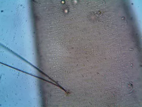
Fouling in solvent-laden MBR trains is not only biological; solvent residues often polymerize on the membrane surface. Most plants we size for ketone-rich paint or pharma wastewater run CIP triggers from transmembrane pressure rise, not from a fixed calendar alone.
How does catalytic ozonation improve COD removal?
Catalytic ozonation cuts hard COD before the biology sees it. Applying 0.5–1.0 mg O₃ per mg of COD partially oxidizes IPA and MEK into more biodegradable acids. That step can cut SMP and EPS fouling by up to 60%. Pairing the MBR with catalytic ozonation for solvent degradation is the usual side-stream or pre-treatment pattern when residual solvents drive rapid flux loss.
Effective management often starts with a pre-treatment DAF system for solvent removal. Dissolved air flotation can remove up to 90% of free-phase non-polar solvents such as hexane and xylene that would otherwise coat fibers. Inside the bioreactor, a PLC-controlled chemical dosing for fouling control executes timed CIP without operator guesswork.
The 2027 protocol for solvent-fouled membranes uses three stages:
- Stage 1: 1–2% NaOH (heated to 60°C) for 2 hours to dissolve organic polymers.
- Stage 2: 0.5% NaOCl for 30 minutes to eliminate bio-growth.
- Stage 3: 0.3% citric acid (pH 2) for 1 hour to remove inorganic scale.
Real-time TOC sensors (0–10,000 mg/L range) on SCADA can start CIP when solvent spikes appear. At a pharmaceutical plant in Zhejiang, that approach cut manual intervention by 70% and extended membrane life by 2.5 years by stopping hard fouling layers early (HydropureWater field data, 2025).
2027 Engineering Specs for Solvent Wastewater MBR Systems
Solvent wastewater MBR design uses more conservative parameters than municipal duty, starting with a 2027 design flux of 12–20 LMH. For high-TOC streams (>5,000 mg/L), apply a 25% derating for viscosity and fouling risk so surges do not plug pores.
Hydraulic retention time must stretch to 6–12 hours, versus 4–8 hours in many municipal plants. The longer HRT gives acclimated biomass time to break solvent chains. MLSS is held at 8–12 g/L; municipal trains often push 15 g/L, but solvent duty benefits from slightly lower solids for oxygen transfer. For broader high-TOC benchmarks, see MBR engineering specs for high-TOC industrial wastewater.
Which COD removal methods suit solvent wastewater?
COD removal methods for solvent streams usually stack physical oil/solvent capture, biological mineralization, and membrane polishing. DAF strips free-phase organics; MBR biology mineralizes dissolved solvents at high sludge age; catalytic ozonation or Fenton cuts refractory COD above about 5,000 mg/L. When residual organics still exceed reuse targets after MBR, some plants add high-strength organic wastewater treatment by reverse osmosis as a polishing step rather than enlarging the bioreactor.
| Engineering Parameter | 2027 Solvent Spec | Standard Industrial Spec | Impact on Compliance |
|---|---|---|---|
| Design Flux (LMH) | 12–20 | 20–30 | Prevents irreversible pore plugging |
| HRT (Hours) | 6–12 | 4–8 | Ensures 99% COD mineralization |
| MLSS (g/L) | 8–12 | 10–15 | Optimizes oxygen transfer in viscous media |
| Energy Demand (kWh/m³) | 0.6–1.2 | 0.4–0.8 | Supports intensive fouling control aeration |
| TOC Removal (%) | >98% | >90% | Meets EU Directive 2010/75/EU |
Energy demand for these systems runs 0.6–1.2 kWh/m³. About 40% of that energy goes to scouring aeration that keeps solvent-driven biofilms off the membrane. Typical effluent—COD <50 mg/L, TSS <10 mg/L, TOC <20 mg/L—meets EPA 40 CFR Part 414 and China's GB 31571-2015. At TSS <1 mg/L and COD <50 mg/L, that effluent also suits cooling-tower makeup, floor washing, or RO feed: a semiconductor fab in Taiwan reuses 80% of its MBR-treated solvent wastewater for non-critical rinse. Always match residual solvent speciation to the reuse water quality limit before piping to process. EU plants should also track TOC against EU Urban Wastewater Treatment Directive updates when discharge points interact with urban works.
MBR vs CAS for Solvent Wastewater: Cost-Benefit Analysis
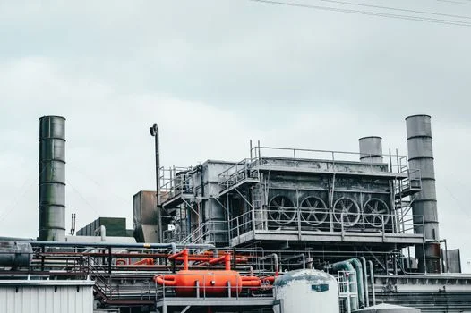
MBR CapEx runs 20–40% higher than a CAS plant of similar hydraulic capacity, yet 10-year ownership cost often favors MBR on solvent duty. For a 200 m³/h plant, MBR CapEx typically spans $1.2M to $4.5M by membrane material. OpEx savings come from sludge, tertiary steps, and avoided non-compliance.
What does COD removal cost in wastewater plants?
COD removal cost in wastewater plants is driven by energy, sludge haulage, chemicals, and effluent surcharges—not membrane list price alone. MBR sludge yield is about 1.5–2.5 kg TSS per kg COD removed versus 3–5 kg on CAS, cutting disposal by up to 70%. Dropping tertiary sand or carbon saves roughly $0.15–$0.30/m³. On tight urban sites, the 60% smaller footprint (0.2–0.4 m²/m³/day) often decides CapEx. Broader industrial wastewater treatment programs should still compare local power and sludge fees.
| Metric | Conventional (CAS + Clarifier) | Solvent-Optimized MBR |
|---|---|---|
| COD Removal Efficiency | 85–90% | 98–99.5% |
| Sludge Yield (kg TSS/kg COD) | 0.4–0.6 | 0.15–0.25 |
| Footprint Required | Baseline (1.00x) | 40% |
| Effluent TSS (mg/L) | 15–30 | <1 |
| Regulatory Risk | High (Settleability dependent) | Zero (Physical barrier) |
A chemical plant in Shanghai reported avoiding over $250,000 per year in non-compliance fines after replacing a failing clarifier train with an MBR. Procurement teams can build a simple ROI model from local electricity ($/kWh), sludge fees ($/ton), and effluent surcharges; payback on high-strength solvent streams typically falls between 18 and 36 months.
Who This Is For and Next Step
Plant engineers, EPC designers, and procurement managers sizing solvent-bearing wastewater from pharma, paint, or specialty chemical lines are the readers this guide serves. Look elsewhere if the load is mostly free product recoverable by distillation alone, or if the site already meets limits with stable CAS settleability and no expansion pressure.
Selection checklist before freezing the design: confirm solvent polarity mix and EC50 risk. Set design flux at 12–20 LMH with high-TOC derating. Choose PVDF, PTFE, or ceramic from immersion data, then lock DAF and ozonation needs for free-phase and hard COD. Budget 0.6–1.2 kWh/m³ including scour, and verify COD <50 mg/L and TSS <10 mg/L against the permit.
If you need a duty-specific membrane and CIP package, send the influent matrix through our request-quote form for a sized proposal.
Frequently Asked Questions
Why choose an MBR membrane bioreactor for solvent laden wastewater over CAS?
An MBR membrane bioreactor for solvent laden wastewater separates solids through a physical membrane barrier, so effluent quality stops depending on floc settleability. PVDF filtration holds TSS below 1 mg/L even during the deflocculation events that drive 30–50% TSS carryover in CAS clarifiers. Running at MLSS of 8–12 g/L raises toxicity resistance, and dropping the clarifier removes the sedimentation constraint that ketones impose.
What solvent tolerant MBR design flux LMH range applies for 2027?
Solvent tolerant MBR design flux for 2027 runs 12–20 LMH, versus 20–30 LMH on standard industrial duty. Streams above 5,000 mg/L TOC take a further 25% derating for viscosity and fouling risk. Mixed-solvent feeds such as methanol plus toluene typically derate another 20–30% to cover the denser fouling matrix. Most solvent plants we size hold the lower end of that band.
Can MBR treat wastewater with >10,000 mg/L COD from solvents?
Yes, but not as a standalone process. Influent with COD >5,000 mg/L should be pre-treated with DAF or advanced oxidation (Fenton or catalytic ozonation) to cut organic load. A pharmaceutical plant in Jiangsu used Fenton oxidation followed by MBR on 12,000 mg/L COD influent and reached 99% total removal. Standalone biology at that strength usually loses flux and nitrification stability.
What is the expected lifespan of PVDF membranes in solvent MBR systems?
PVDF membranes last 5–7 years when automated CIP and catalytic ozonation follow 2027-standard fouling control. Ceramic membranes can last 10–15 years but need a much higher initial outlay (about 3–5x). Lifespan shortens when free-phase solvents bypass pretreatment or when NaOCl and caustic CIP are skipped after TMP alarms.
What are the key compliance standards for solvent wastewater discharge?
Major benchmarks include EPA 40 CFR Part 414 (COD <200 mg/L for organic chemicals), EU Directive 2010/75/EU (TOC <50 mg/L), and China's GB 31571-2015 (COD <60 mg/L for the chemical industry). MBR trains are designed to meet these limits with a physical solids barrier rather than relying on clarifier settleability alone.