An MBR system for sewage treatment combines activated sludge with submerged microfiltration or ultrafiltration membranes (0.01–0.4 μm pore size) to produce near-reuse-quality effluent. Typical municipal designs report 92–97% TSS removal and 90–95% COD reduction, with energy use often in the 0.6–1.2 kWh/m³ range and about 60% less footprint than conventional activated sludge. Membrane filtration separates biomass from permeate, so secondary clarifiers are not required and mixed liquor suspended solids (MLSS) can run at 8,000–12,000 mg/L.
How an MBR System for Sewage Treatment Works
An MBR couples biological oxidation with membrane solids separation, so secondary clarifiers are unnecessary. Screened sewage moves through anoxic and aerobic zones, then through submerged MF/UF membranes at 10–50 kPa. Municipal flux is typically 15–30 LMH; industrial streams often run 10–20 LMH. Effluent commonly stays below 1 mg/L TSS and 50 mg/L COD.
What is the MBR working principle?
The MBR working principle is continuous biological degradation of organics and nutrients, followed by physical membrane retention of biomass and particulates. Recycle from the aerobic zone feeds nitrate to the anoxic zone for denitrification, while fine-bubble aeration supplies oxygen for BOD/COD oxidation. Suction-driven membranes then withdraw clarified permeate and keep high MLSS in the tanks.
Most plants we size for municipal sewage keep the aerobic zone at the lower end of the 4–8 hour HRT band unless peak organic load forces a longer residence time. A packaged MBR Membrane Bioreactor Wastewater Treatment System follows the same sequence in a compact footprint.
Influent Screening
Raw sewage first passes mechanical bar screens with 3–6 mm apertures. Rags, plastics, and grit must be removed here, or they abrade and plug membrane channels. Rotary drum or step screens are common when membrane warranty conditions demand tight pretreatment.
Anoxic Zone
After screening, flow enters the anoxic zone for denitrification. Hydraulic retention time is typically 2–4 hours, with dissolved oxygen held below 0.5 mg/L. Nitrate-rich mixed liquor returns from the aerobic zone so denitrifiers convert nitrate to nitrogen gas. MLSS in this zone usually stays in the 8,000–12,000 mg/L band used across the biological train.
Aerobic Zone
The aerobic zone provides the main BOD and COD oxidation. HRT is commonly 4–8 hours at a dissolved oxygen setpoint of 1.5–3 mg/L from fine-bubble aeration. Air flow often falls between 0.1–0.3 m³/m³/min, sized to the oxygen demand of the high-MLSS inventory. That dense biomass is why MBR tanks stay smaller than clarifier-based trains treating the same load.
Membrane Filtration
Submerged microfiltration or ultrafiltration membranes (0.01–0.4 μm) separate permeate from concentrated biomass. Filtration is usually suction-driven at a transmembrane pressure of 10–50 kPa. Municipal sewage designs often target 15–30 LMH; industrial wastewater is more often held at 10–20 LMH when fouling risk is higher.
Effluent Quality and Sludge Management
Well-operated MBR effluent commonly achieves less than 1 mg/L TSS and less than 50 mg/L COD under municipal design conditions. BOD is often below 10 mg/L, with fecal coliforms below 1,000 CFU/100 mL. Waste activated sludge is withdrawn at about 1–1.2% total solids. Yield is typically 0.05–0.1 kg TSS per kg COD removed, and that thicker WAS still needs dewatering before hauling.
| MBR Process Stage | Key Parameter | Typical Range/Value |
|---|---|---|
| Influent Screening | Bar Screen Aperture | 3–6 mm |
| Anoxic Zone | Hydraulic Retention Time (HRT) | 2–4 hours |
| Anoxic Zone | Dissolved Oxygen (DO) | <0.5 mg/L |
| Aerobic Zone | Hydraulic Retention Time (HRT) | 4–8 hours |
| Aerobic Zone | Dissolved Oxygen (DO) | 1.5–3 mg/L |
| Aerobic Zone | Aeration Air Flow Rate | 0.1–0.3 m³/m³/min |
| Biological Zones (Overall) | Mixed Liquor Suspended Solids (MLSS) | 8,000–12,000 mg/L |
| Membrane Filtration | Membrane Pore Size | 0.01–0.4 μm |
| Membrane Filtration | Transmembrane Pressure (TMP) | 10–50 kPa |
| Membrane Filtration | Flux Rate (Municipal Sewage) | 15–30 LMH |
| Membrane Filtration | Flux Rate (Industrial Wastewater) | 10–20 LMH |
What Are Typical MBR Membrane Specs?
Typical MBR membrane specs split into hollow fiber and flat sheet families, and the choice changes packing density, cleaning frequency, and fouling behavior. Pore size, flux, energy, and solids tolerance differ enough that the wrong format raises OPEX even when biology is sound.
Hollow Fiber Membranes
Hollow fiber membranes, usually PVDF or PE, commonly use 0.1–0.4 μm pores. High packing density yields large area in a small cassette, with municipal flux often 15–30 LMH and energy around 0.6–0.9 kWh/m³. Individual elements often provide 8–16 m². Chemical cleans every 3–6 months are common because finer channels trap more debris, yet MLSS tolerance can reach about 15,000 mg/L on robust municipal trains.
Flat Sheet Membranes
Flat sheet membranes, often PVDF or PTFE, typically use 0.01–0.1 μm pores. Flux is usually 10–20 LMH, with energy nearer 0.8–1.2 kWh/m³. Cassette units often provide 80–225 m². Wider channels scour more easily, so fouling rates can be lower, but oils and grease foul flat sheets hard. Service life is often quoted at 7–10 years versus 5–8 years for hollow fiber, with replacement around $50–$100/m² for both formats.
Fouling Resistance and Cleaning Protocols
Maintenance cleaning usually soaks membranes in sodium hypochlorite at 500–2,000 ppm for 1–2 hours on a weekly cycle. Recovery cleaning may use 1–2% citric acid or 1,000–2,000 ppm NaOCl for 4–6 hours each quarter. Flat sheet modules are often preferred for high-solids or oily industrial streams such as landfill leachate or slaughterhouse effluent. HydropureWater supplies both integrated MBR systems with submerged PVDF membranes and DF series flat sheet membrane modules for high-solids industrial wastewater when project conditions diverge.
| Feature | Hollow Fiber Membranes | Flat Sheet Membranes |
|---|---|---|
| Material | PVDF, PE | PVDF, PTFE |
| Pore Size | 0.1–0.4 μm | 0.01–0.1 μm |
| Typical Flux Rate | 15–30 LMH | 10–20 LMH |
| Energy Consumption | 0.6–0.9 kWh/m³ | 0.8–1.2 kWh/m³ |
| Module/Cassette Size | 8–16 m² per element | 80–225 m² per unit |
| Fouling Resistance | Requires more frequent chemical cleaning | Lower fouling rates, sensitive to oils/grease |
| MLSS Tolerance | Up to 15,000 mg/L | Generally lower tolerance to high FOG |
| Lifespan | 5–8 years | 7–10 years |
| Replacement Cost | $50–$100/m² | $50–$100/m² |
| Typical Use Cases | Municipal sewage, food processing | Industrial wastewater (landfill leachate, slaughterhouse effluent) |
MBR vs. Conventional Activated Sludge: Performance, Cost, and Footprint Comparison
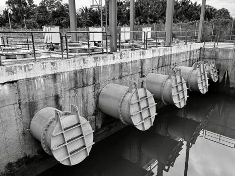
MBR systems usually beat conventional activated sludge on effluent quality and land use, while CAPEX and membrane aeration energy run higher. The decision turns on discharge or reuse limits, available plot area, and who owns long-term OPEX.
Effluent Quality
MBR effluent commonly stays below 1 mg/L TSS and 50 mg/L COD, which supports direct discharge or reuse polishing. Conventional activated sludge more often leaves 10–30 mg/L TSS and 60–120 mg/L COD, so tertiary filters and disinfection are added when permits tighten. That quality gap is why constrained reuse projects shortlist MBR early.
Footprint and Energy Use
MBR plants typically need 0.5–1 m²/m³/day versus 1.5–2.5 m²/m³/day for CAS, about 60% less land. Clarifiers disappear and MLSS rises to 8,000–12,000 mg/L versus 2,000–4,000 mg/L. Design energy for MBR is often 0.6–1.2 kWh/m³ versus 0.3–0.6 kWh/m³ for CAS without tertiary stages. Membrane scouring alone may take 0.4–0.8 kWh/m³. A full-plant municipal case study reported 1.44 kWh/m³ average before optimization, with a path toward about 0.84 kWh/m³ after aeration upgrades (WaterWorld, Dundee WWTP).
Capital and Operating Costs
Capital cost for MBR capacity is often $1,500–$3,000/m³/day versus $800–$1,500/m³/day for CAS on 2025 market ranges used in project screening. Operating cost is commonly $0.20–$0.40/m³ for MBR versus $0.10–$0.25/m³ for CAS. Sludge disposal can fall 20–30% because WAS is thicker and yield is lower. Membrane replacement alone is often modeled at $0.03–$0.05/m³ over membrane life.
Compliance and Water Reuse
MBR permeate frequently meets reuse targets such as California Title 22 without a separate tertiary filter. US EPA publishes national water-reuse guidance that planners use with state rules for fit-for-purpose quality. According to US EPA LCA work on decentralized MBR systems, recycled permeate can displace about 0.94–0.96 m³ of drinking water per m³ treated (EPA/600/R-16/243). CAS usually needs extra filtration and disinfection to reach the same reuse class.
| Feature | MBR System | Conventional Activated Sludge (CAS) |
|---|---|---|
| Effluent TSS | <1 mg/L | 10–30 mg/L |
| Effluent COD | <50 mg/L | 60–120 mg/L |
| Footprint Requirement | 0.5–1 m²/m³/day (60% less) | 1.5–2.5 m²/m³/day |
| MLSS Concentration | 8,000–12,000 mg/L | 2,000–4,000 mg/L |
| Energy Consumption | 0.6–1.2 kWh/m³ | 0.3–0.6 kWh/m³ (excluding tertiary) |
| Aeration Energy | 0.4–0.8 kWh/m³ | 0.2–0.4 kWh/m³ |
| Capital Cost | $1,500–$3,000/m³/day | $800–$1,500/m³/day |
| Operating Cost | $0.20–$0.40/m³ | $0.10–$0.25/m³ |
| Sludge Disposal Cost Reduction | 20–30% reduction | Standard rates |
| Compliance for Reuse | Meets reuse standards directly | Requires tertiary treatment & disinfection |
Design Parameters for MBR Systems: Influent, Membrane, and Operational Specs
MBR design locks influent limits, membrane flux, aeration, and cleaning into one operating envelope. Engineers reviewing bids should match each vendor curve to measured wastewater data, not brochure averages.
Influent Characteristics and Limitations
Municipal and light industrial MBR feeds commonly sit at 200–1,000 mg/L COD, 100–500 mg/L BOD, and 100–500 mg/L TSS. Practical membrane limits are usually less than 100 mg/L FOG, less than 500 mg/L salinity, and pH 6–9. When FOG runs higher, add upstream dissolved air flotation (DAF) systems for effective MBR pretreatment and high-FOG wastewater before the membranes see free oil.
Membrane Flux and Transmembrane Pressure (TMP)
Design flux is typically 15–30 LMH for municipal sewage and 10–20 LMH for industrial wastewater. Peak flux of 25–40 LMH is often allowed for only 2–4 hours. Normal TMP sits at 10–50 kPa; a climb to 50–80 kPa is the usual cleaning trigger on plants we commission.
Aeration and Mixed Liquor Suspended Solids (MLSS)
Coarse-bubble scouring air at 0.1–0.3 m³/m³/min protects the membrane surface. Fine-bubble biological air at 0.4–0.8 m³/m³/min supports oxidation. Municipal MLSS is commonly 8,000–12,000 mg/L; industrial trains may hold 10,000–15,000 mg/L. Sludge retention time of 15–30 days is typical for MBR, versus 5–15 days for CAS.
Cleaning Protocols
Weekly maintenance cleaning often uses 200–500 ppm NaOCl for 1–2 hours by backflush or soak. Quarterly recovery cleaning uses 1,000–2,000 ppm NaOCl or 1–2% citric acid for 4–6 hours. A PLC-controlled chemical dosing for MBR membrane cleaning and maintenance keeps dose, contact time, and records consistent across shifts.
| Parameter Category | Specific Parameter | Typical Design Range/Value |
|---|---|---|
| Influent Characteristics | COD | 200–1,000 mg/L |
| Influent Characteristics | BOD | 100–500 mg/L |
| Influent Characteristics | TSS | 100–500 mg/L |
| Influent Limitations | FOG | <100 mg/L |
| Influent Limitations | Salinity | <500 mg/L |
| Influent Limitations | pH | 6–9 |
| Membrane Operation | Normal Flux (Municipal) | 15–30 LMH |
| Membrane Operation | Normal Flux (Industrial) | 10–20 LMH |
| Membrane Operation | Peak Flux (Short-term) | 25–40 LMH (2–4 hours) |
| Membrane Operation | Normal Transmembrane Pressure (TMP) | 10–50 kPa |
| Membrane Operation | Cleaning Transmembrane Pressure (TMP) | 50–80 kPa |
| Aeration | Membrane Scouring Air Flow | 0.1–0.3 m³/m³/min |
| Aeration | Biological Treatment Air Flow | 0.4–0.8 m³/m³/min |
| Biological Parameters | MLSS (Municipal) | 8,000–12,000 mg/L |
| Biological Parameters | MLSS (Industrial) | 10,000–15,000 mg/L |
| Biological Parameters | Sludge Retention Time (SRT) | 15–30 days |
| Cleaning Protocols | Maintenance Cleaning (NaOCl) | 200–500 ppm (1–2 hours weekly) |
| Cleaning Protocols | Recovery Cleaning (NaOCl) | 1,000–2,000 ppm (4–6 hours quarterly) |
| Cleaning Protocols | Recovery Cleaning (Citric Acid) | 1–2% (4–6 hours quarterly) |
How to Choose an MBR System for Your Sewage Project
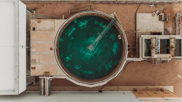
Selecting an MBR system for sewage treatment is a multi-criteria engineering decision, not a single CAPEX comparison. Walk the six checks below with measured influent data and a written effluent target before freezing membrane format or tank volume.
Step 1: Define Effluent Requirements
Write the permit or reuse specification first. Reuse for irrigation or process water usually needs less than 1 mg/L TSS and less than 50 mg/L COD, which MBR can deliver when biology is stable. Sensitive receiving waters or strict sewer ordinances also favor MBR over clarifier trains. Regional municipal references such as engineering specs for municipal MBR projects in the USA help frame local expectations.
Step 2: Characterize Influent and Select Membrane Type
Measure COD, BOD, TSS, FOG, salinity, and pH on representative days, not a single grab. Hollow fiber is often the lower-CAPEX choice for municipal sewage and moderate-FOG food wastewater. Flat sheet is usually safer for high-solids or oily industrial streams. Pretreatment such as DAF belongs in the scope when FOG exceeds about 100 mg/L.
Step 3: Calculate Footprint Constraints
Confirm usable plot area early. MBR typically needs 0.5–1 m²/m³/day, about 60% less than the 1.5–2.5 m²/m³/day CAS range. On tight urban or factory sites, that difference often decides the process before energy is even modeled.
Step 4: Estimate Energy Budget
Budget 0.6–1.2 kWh/m³ for MBR versus 0.3–0.6 kWh/m³ for CAS without tertiary stages. Include the energy CAS would spend on filters and UV if the same effluent class is required. Proportional membrane aeration and DO control are the levers that pull real plants toward the lower end of the MBR band.
Step 5: Evaluate Capital and Operating Costs
Screen CAPEX at $1,500–$3,000/m³/day for MBR and $800–$1,500/m³/day for CAS. Then model OPEX at $0.20–$0.40/m³ versus $0.10–$0.25/m³. Credit 20–30% sludge disposal savings and $0.03–$0.05/m³ membrane replacement in the life-cycle comparison.
Step 6: Assess Maintenance Capacity and Vendor Support
Confirm who will run weekly chemical cleans and who stocks spare modules. Hollow fiber often needs more frequent chemical attention; flat sheet may tolerate longer intervals but still needs recovery cleans. Use a structured supplier review such as a regional supplier selection guide for MBR systems before award.
Selection checklist: Confirm effluent or reuse limits and a full influent profile including FOG. Match membrane format to solids and oil risk, and check footprint at 0.5–1 m²/m³/day. Model scour-air energy, membrane replacement, chemical OPEX, and local spares plus cleaning labor.
Who this is for: plant engineers, EPC teams, and procurement managers sizing municipal or industrial sewage plants that need reuse-quality permeate or a small footprint. Who should look elsewhere: sites with very high FOG and no budget for pretreatment, or projects where loose secondary limits make CAS plus simple clarification clearly cheaper. Next step: send flow, COD/BOD/TSS/FOG, and discharge targets through our MBR system design inquiry so sizing and membrane format can be checked against your data.
Frequently Asked Questions
What is the typical lifespan of MBR membranes?
MBR membrane life is typically 5–10 years when cleaning and pretreatment stay inside design limits. Hollow fiber modules commonly last 5–8 years, while flat sheet modules are often quoted at 7–10 years. Aggressive FOG, sand, or missed recovery cleans shorten that window faster than raw flux setpoints alone.
How often do MBR membranes need cleaning?
Most plants schedule weekly maintenance cleaning with 200–500 ppm NaOCl for 1–2 hours by soak or chemically enhanced backwash. Recovery cleaning every quarter, or when TMP reaches 50–80 kPa, uses 1,000–2,000 ppm NaOCl or 1–2% citric acid for 4–6 hours. Skipping recovery cleans to save chemicals usually costs more in flux loss later.
Can MBR systems handle fluctuating influent loads?
Yes. High MLSS at 8,000–12,000 mg/L and SRT of 15–30 days give MBR trains more buffering than low-MLSS CAS plants. Peak flux of 25–40 LMH for 2–4 hours covers short hydraulic spikes if screening and scour air remain online. Sustained organic or FOG shocks still need equalization or pretreatment.
What are the main advantages of MBR over conventional activated sludge?
The main advantages are effluent quality suitable for reuse, about 60% less footprint, and stable solids separation without secondary clarifiers. MBR also removes a separate tertiary filter stage for many reuse permits. The trade-off is higher CAPEX and membrane aeration energy that must be optimized in controls.
Is MBR effluent suitable for reuse?
Yes. MBR permeate typically reaches very low TSS, BOD, and COD with strong pathogen reduction from the membrane barrier, so it fits many non-potable reuse schemes when disinfection is added as required. Planners still align local reuse codes and US EPA water-reuse guidance with the intended end use. California Title 22 projects often use MBR as the core solids barrier before UV or chlorine.