TFT-LCD Wastewater Engineering Solution 2026: Hybrid ZLD System with 99.9% MEA & Phosphate Removal
TFT-LCD wastewater engineering solutions in 2026 focus on hybrid zero liquid discharge (ZLD) systems that remove 99.9% of monoethanolamine (MEA) and phosphate—key contaminants from etching and cleaning processes. Fluidized-bed Fenton and electro-Fenton processes achieve 92-98% COD reduction at influent concentrations of 50-500 mg/L MEA and 10-100 mg/L phosphate (per 2024 EPA benchmarks). These systems integrate dissolved air flotation (DAF), membrane bioreactors (MBR), and reverse osmosis (RO) to meet China’s GB 31573-2015, EU Industrial Emissions Directive 2010/75/EU, and U.S. EPA discharge limits for semiconductor fabs.
Why TFT-LCD Wastewater Requires Specialized Engineering Solutions
TFT-LCD wastewater typically contains concentrations of 50-500 mg/L monoethanolamine (MEA) and 10-100 mg/L phosphate, which significantly exceed the inhibitory thresholds for standard biological treatment units. MEA, widely used as a stripping agent and photoresist developer, contributes to high chemical oxygen demand (COD) and organic nitrogen levels. Because MEA possesses a stable molecular structure, conventional activated sludge systems often achieve less than 30% removal efficiency (per 2024 industry benchmarks), leading to persistent regulatory exceedances. When MEA and phosphate are present simultaneously, they create a complex chemical environment that can foul membranes and inhibit the nitrification-denitrification cycle in biological reactors.
The presence of phosphate in etching and cleaning wastewater poses a severe risk of eutrophication in local water bodies. Most TFT-LCD fabs utilize phosphoric acid-based etchants, resulting in effluent streams that fluctuate rapidly in pH and nutrient concentration. Unlike PCB wastewater ZLD system designs with copper recovery, TFT-LCD treatment must prioritize the stabilization of these organic amines and inorganic phosphorus compounds before they reach the final discharge point.
Regulatory pressure is escalating globally. In 2025, a major TFT-LCD fabrication facility in Suzhou, China, was assessed $1.2 million in environmental penalties after its phosphate discharge exceeded the GB 31573-2015 limit of 0.5 mg/L for three consecutive weeks. The failure was attributed to an undersized chemical precipitation unit that could not handle the peak MEA-phosphate complexation. This scenario underscores the necessity for specialized engineering that moves beyond simple pH adjustment toward advanced oxidation and hybrid membrane separation.
the high salinity of TFT-LCD effluent, often exceeding 3,000 mg/L Total Dissolved Solids (TDS), necessitates a ZLD approach to protect local infrastructure. Engineers must account for the specific inhibition mechanisms where MEA acts as a chelating agent, preventing the precipitation of phosphate ions unless high-energy advanced oxidation processes (AOPs) are employed to break the organic bonds first. This requirement is similar to the challenges found in TMAH wastewater treatment cost breakdowns and ROI calculations, where specialized catalysts are required for total nitrogen removal.
Hybrid ZLD System Design for TFT-LCD Wastewater: Step-by-Step Process Flow
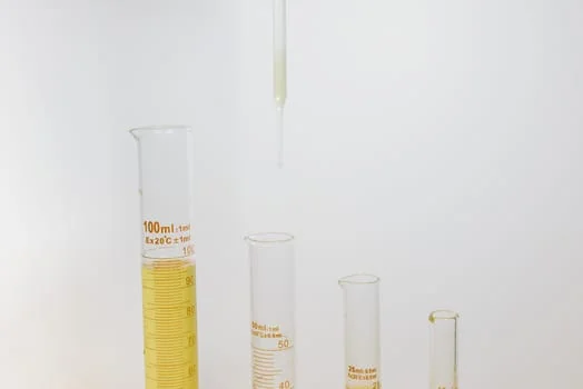
The hybrid ZLD treatment train for TFT-LCD facilities involves a multi-stage process that integrates physical separation, advanced oxidation, and membrane filtration to achieve 99.9% contaminant removal. This modular design allows facility managers to scale treatment capacity as fab production increases, while maintaining strict control over effluent quality. The following steps outline the standard engineering flow for a 2026-compliant system.
Step 1: Pretreatment and Solids Removal. The influent first passes through a rotary mechanical bar screen (GX Series) to remove large debris and photoresist fragments. This protects downstream pumps and prevents clogging in the oxidation reactors. For high-volume fabs, a mesh size of 1-3 mm is recommended to ensure minimal head loss while capturing 98% of macro-solids.
Step 2: Primary Separation via DAF. A high-efficiency DAF system for TFT-LCD wastewater pretreatment is utilized to remove fats, oils, grease (FOG), and suspended solids. By injecting micro-bubbles (20-50 μm), the DAF system achieves a 95% reduction in total suspended solids (TSS) at flow rates ranging from 4 to 300 m³/h. This step is critical for reducing the organic load on the Fenton reactor.
Step 3: Advanced Oxidation (Fenton/Electro-Fenton). This is the core of the MEA removal process. In the fluidized-bed Fenton reactor, hydrogen peroxide and ferrous sulfate are added at a controlled pH of 3.0. Hydroxyl radicals (•OH) aggressively attack the MEA molecules and break the phosphate complexes. Retention times are typically set between 90 and 120 minutes to ensure maximum mineralization of COD.
Step 4: Biological Polishing. Following oxidation, the wastewater is neutralized and sent to an MBR system. Utilizing submerged PVDF MBR modules for TFT-LCD wastewater polishing, the system removes residual BOD and COD. The 0.1 μm pore size provides a complete barrier to bacteria and suspended solids, ensuring 99% microbial removal and a silt density index (SDI) suitable for reverse osmosis.
Step 5: Membrane Concentration and Permeate Recovery. The RO systems for final permeate polishing and brine concentration in TFT-LCD ZLD achieve a 95% recovery rate. The permeate is often high enough quality to be recycled back to the fab's cooling towers or for low-grade cleaning processes, significantly reducing fresh water intake. The concentrated brine is then directed to a crystallizer or evaporator for final ZLD.
Step 6: Sludge Management. Residual solids from the DAF and Fenton processes are processed using a plate-and-frame filter press. This produces a dry cake with 30-40% solids content, minimizing disposal costs and ensuring that all liquid is recovered and returned to the head of the system.
| Process Stage | Equipment Series | Target Contaminant | Removal Efficiency |
|---|---|---|---|
| Pretreatment | GX Rotary Screen | Large Solids/Debris | >98% |
| Primary Clarification | DAF System | TSS, FOG, Photoresist | 95% TSS |
| Advanced Oxidation | Fluidized-Bed Fenton | MEA, COD, Complexed P | 92-98% COD |
| Secondary Biological | DF Series MBR | Residual BOD, Bacteria | 99% Microbial |
| Tertiary Polishing | JY Series RO | TDS, Dissolved Salts | 95% Recovery |
Fenton vs. Electro-Fenton for MEA and Phosphate Removal: Performance Comparison
Fluidized-bed Fenton processes achieve a 98.9% MEA removal rate at an optimal pH of 3.0 within a 120-minute hydraulic retention time. This efficiency is driven by the high surface area of the fluidized carrier, which promotes the crystallization of iron phosphate and reduces the volume of chemical sludge produced compared to traditional batch Fenton reactors. For facilities processing more than 100 m³/h, the fluidized-bed approach is the engineering standard due to its lower footprint and continuous operation capability.
Electro-Fenton (EF) technology offers a compelling alternative for smaller fabs or specialized waste streams. In an EF reactor, hydrogen peroxide is generated in situ at the cathode, while ferrous ions are released from a sacrificial anode or added as a catalyst. This process typically achieves 92-97% COD removal from actual TFT-LCD wastewater. The primary advantage of EF is the reduction in chemical handling and the lower volume of sludge generated, as the iron dosage can be precisely controlled via electrical current. However, energy consumption is significantly higher, often ranging from 2.5 to 5.0 kWh/m³ depending on the influent concentration.
When comparing the two for phosphate removal, the fluidized-bed Fenton process generally performs better in high-phosphate environments (100 mg/L+) because the fluidized media serves as a nucleation site for calcium phosphate or ferric phosphate precipitation. This prevents the "sludge bulking" often seen in conventional systems. For engineers designing IC etching wastewater treatment solutions with hybrid ZLD designs, the choice between Fenton and Electro-Fenton often hinges on the specific ratio of MEA to fluoride or phosphate in the influent.
| Parameter | Fluidized-Bed Fenton | Electro-Fenton (EF) | Biological (Control) |
|---|---|---|---|
| MEA Removal (%) | 98.9% | 94-96% | <30% |
| COD Reduction (%) | 92-98% | 90-97% | 40-60% |
| Energy Use (kWh/m³) | 0.5 - 1.2 | 2.5 - 5.0 | 0.8 - 1.5 |
| Sludge Production | Moderate (Crystalline) | Low | High (Biosolids) |
| Optimal Flow Rate | >100 m³/h | <50 m³/h | Any |
Regulatory Compliance for TFT-LCD Wastewater: China, EU, and U.S. Standards
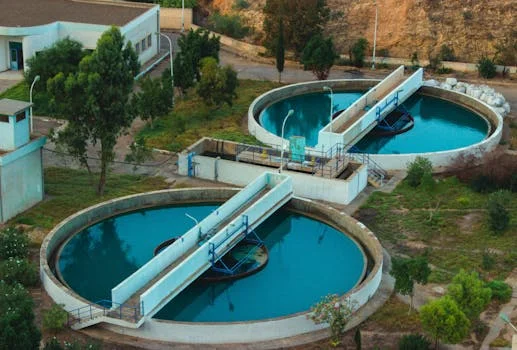
China’s GB 31573-2015 standard mandates that semiconductor effluent must maintain MEA levels below 1 mg/L and total phosphorus below 0.5 mg/L. These limits are among the strictest in the world, reflecting the high density of electronics manufacturing in regions like the Yangtze River Delta. Meeting these standards requires a multi-barrier approach where the Fenton process handles the bulk removal and the MBR/RO stages provide the final polishing necessary to reach sub-ppm levels.
In the European Union, the Industrial Emissions Directive (2010/75/EU) and the associated Best Available Techniques (BAT) Reference Documents (BREF) set the framework for TFT-LCD discharge. While individual permits vary by member state, the general BAT-Associated Emission Levels (BAT-AELs) target phosphate concentrations below 2 mg/L and COD below 125 mg/L. European fabs are increasingly adopting ZLD configurations to comply with the Circular Economy Action Plan, which incentivizes water reuse within the industrial site.
The U.S. EPA regulates semiconductor fabs under Clean Water Act (CWA) 40 CFR Part 469. While federal categorical limits focus heavily on Toxic Organics (TTOs) and Fluoride, local National Pollutant Discharge Elimination System (NPDES) permits often impose much stricter MEA limits (typically <10 mg/L) and phosphate limits (<1 mg/L) to prevent oxygen depletion in receiving streams. A 2025 case study from a fab in Taiwan demonstrated that by upgrading to a hybrid ZLD system, they were able to reduce MEA from an influent of 300 mg/L to an effluent of <0.1 mg/L, comfortably exceeding all global regulatory requirements.
| Contaminant | China (GB 31573) | EU (IED 2010/75) | U.S. (NPDES/EPA) | ZLD Target (2026) |
|---|---|---|---|---|
| MEA (mg/L) | <1.0 | Case-by-case | <10.0 | <0.1 |
| Phosphate (mg/L) | <0.5 | <2.0 | <1.0 | <0.05 |
| COD (mg/L) | <50 | <125 | <100 | <10 |
| TSS (mg/L) | <30 | <35 | <20 | <1 |
| pH | 6.0 - 9.0 | 6.5 - 9.5 | 6.0 - 9.0 | 7.0 - 8.0 |
CAPEX and OPEX Breakdown for TFT-LCD Wastewater ZLD Systems
The CAPEX for a 500 m³/h TFT-LCD ZLD system typically ranges from $5.5M to $8.0M, depending on the required level of automation and membrane redundancy. For smaller facilities (50 m³/h), the initial investment starts at approximately $1.5M. The primary cost drivers are the fluidized-bed reactor metallurgy (required to resist corrosion at pH 3), the total surface area of the MBR and RO membranes, and the integration of SCADA systems for real-time monitoring of MEA and phosphate concentrations.
Operating expenses (OPEX) are dominated by energy and chemical consumption. Energy costs for electro-Fenton systems are particularly sensitive to electricity pricing, often accounting for 40-50% of the total OPEX. In contrast, fluidized-bed Fenton systems have higher chemical costs, specifically for high-purity hydrogen peroxide and pH adjustment reagents (sulfuric acid and sodium hydroxide). On average, chemical costs range from $0.50 to $1.20 per cubic meter of treated water. (HydropureWater field data, 2025).
The ROI for a hybrid ZLD system is typically realized within 3 to 5 years for large-scale fabs. This calculation includes the direct savings from reclaimed water (reducing municipal water purchases), the avoidance of environmental non-compliance penalties, and the reduction in sludge disposal fees through advanced dewatering. Fabs that reuse 90% of their treated effluent can offset up to 30% of their annual operating costs through water savings alone.
| Cost Category | Percentage of OPEX | Estimated Cost/m³ | Key Drivers |
|---|---|---|---|
| Energy | 40% | $0.30 - $0.80 | Pump head, EF current, RO pressure |
| Chemicals | 30% | $0.50 - $1.20 | H2O2, FeSO4, NaOH, Antiscalants |
| Labor | 20% | $0.15 - $0.30 | Maintenance, monitoring, lab testing |
| Maintenance | 10% | $0.05 - $0.15 | Membrane cleaning (CIP), parts |
How to Select the Right TFT-LCD Wastewater Treatment System for Your Fab
Selecting the optimal wastewater treatment architecture requires a quantitative assessment of influent MEA/phosphate loading, local discharge permit stringency, and the facility's total water recovery targets. For fabs with high-volume, low-concentration streams, a focus on high-flux MBR and RO may be sufficient. However, for fabs utilizing concentrated MEA strippers, the inclusion of a fluidized-bed Fenton reactor is non-negotiable to prevent biological system failure.
Facility managers must also consider the physical footprint available for the treatment plant. Fluidized-bed systems are vertical and compact, making them ideal for urban fabs with limited land. Conversely, if energy costs are low and chemical storage is restricted by local safety codes, an electro-Fenton system may be the superior choice despite its higher power demand. The following decision matrix provides a framework for initial system selection.
| Selection Factor | Low Load (<50 mg/L MEA) | High Load (>200 mg/L MEA) | ZLD Requirement |
|---|---|---|---|
| Primary Tech | MBR + RO | Fenton + MBR + RO | Fenton + MBR + RO + Evap |
| Preferred Oxidation | Electro-Fenton | Fluidized-Bed Fenton | Fluidized-Bed Fenton |
| Automation Level | Standard | Advanced (Real-time MEA) | Full SCADA Integration |
| Membrane Type | Spiral Wound RO | High-Rejection RO | Disc-Tube (DTRO) for Brine |
Vendor selection should prioritize manufacturers who offer turnkey solutions and modular equipment. A comprehensive checklist for evaluating a wastewater partner includes: 1) Proven performance data in TFT-LCD applications, 2) Availability of pilot-scale units for on-site testing, 3) Integrated sludge dewatering capabilities, and 4) 24/7 technical support for membrane maintenance. Ensuring the vendor can provide the full treatment train—from the GX rotary screen to the JY series RO—guarantees system compatibility and simplifies the compliance audit process.
Frequently Asked Questions
What is the optimal pH for the Fenton process in TFT-LCD wastewater treatment?
The optimal pH is 3.0. At this acidic level, the generation of hydroxyl radicals is maximized, and the oxidation of MEA is most efficient. Deviating to a pH above 4.0 leads to the premature precipitation of ferric hydroxide, which stops the catalytic reaction and increases sludge volume.
How much does a 200 m³/h TFT-LCD ZLD system cost to operate?
The average OPEX is between $1.00 and $2.45 per cubic meter. For a 200 m³/h system operating 24/7, this equates to an annual operating budget of approximately $1.7M to $4.2M, depending on local chemical and energy prices.
Can MBR systems alone remove MEA from TFT-LCD wastewater?
No. MEA is a bio-inhibitory compound at high concentrations. Standard MBR systems typically achieve less than 30% removal because the microbes cannot break down the MEA molecule quickly enough. Pretreatment with Fenton oxidation is required to transform MEA into biodegradable intermediates.
What is the typical lifespan of RO membranes in a TFT-LCD ZLD system?
With proper pretreatment (DAF and MBR), RO membranes typically last 3 to 5 years. However, if the Fenton process is not optimized and residual iron or hydrogen peroxide reaches the membranes, the lifespan can be reduced to less than 12 months due to oxidative damage or mineral scaling.