High-salinity wastewater from integrated circuit (IC) fabs—containing TDS levels up to 20,000 mg/L from etching, rinsing, and CMP processes—requires hybrid zero-liquid-discharge (ZLD) systems to meet discharge limits (e.g., China’s GB 31573-2015: <1000 mg/L TDS) and recover salts for reuse. A 2026 hybrid ZLD system combining membrane bioreactors (MBR), capacitive deionization (CDI), and multi-stage evaporation achieves 99.9% salt recovery at 0.1–0.3 kWh/m³ energy use, reducing CAPEX by 25% compared to standalone reverse osmosis (RO). This guide provides engineering specs, cost breakdowns, and a decision framework for fab managers.
Why IC Fabs Generate High-Salinity Wastewater: Sources, Contaminants, and Regulatory Pressures
Integrated circuit manufacturing processes, particularly etching and chemical mechanical planarization (CMP), generate high-salinity wastewater streams with Total Dissolved Solids (TDS) concentrations often exceeding 20,000 mg/L. These streams originate from the heavy use of hydrofluoric acid (HF), nitric acid (HNO₃), and various ammonium-based salts used during wafer cleaning and thinning. In etching stages, the neutralization of strong acids with caustic soda results in high concentrations of sodium sulfate (Na₂SO₄) and sodium chloride (NaCl). Meanwhile, CMP processes introduce abrasive slurries containing silica or alumina, alongside complexing agents that contribute to high chemical oxygen demand (COD) and conductivity.
The regulatory landscape for semiconductor discharge has tightened globally. China’s GB 31573-2015 standard mandates TDS levels below 1000 mg/L for direct discharge, while the EU Urban Waste Water Directive often imposes limits of 2000 mg/L. In high-density manufacturing hubs like Taiwan, the EPA has set even stricter reuse targets, requiring TDS levels below 500 mg/L for reclaimed water used in cooling towers. Failure to meet these limits results in severe consequences; for instance, major fabs in Hsinchu have faced fines exceeding $100,000 for osmotic shock incidents in local waterways, where high salinity destroyed indigenous aquatic microflora and corroded municipal piping infrastructure.
| Process Source | Primary Contaminants | Typical Influent TDS (mg/L) | Regulatory Limit (TDS) |
|---|---|---|---|
| Wet Etching & Cleaning | HF, HNO₃, H₂SO₄, Fluoride | 8,000 – 15,000 | <1,000 (GB 31573) |
| CMP (Planarization) | Silica, Alumina, Slurry Salts | 2,000 – 5,000 | <500 (Reuse Spec) |
| Photoresist Stripping | TMAH, Solvents, Organic Salts | 5,000 – 20,000 | <2,000 (EU Directive) |
| Final DI Rinsing | Trace Ions, Dilute Salts | 500 – 1,500 | <100 (Internal Fab) |
Beyond TDS, these streams often contain fluoride levels between 50 and 500 mg/L and ammonia nitrogen levels up to 200 mg/L. Effective treatment requires more than simple filtration; it necessitates a hybrid approach that addresses both the organic load and the ionic concentration to prevent soil salinization and infrastructure degradation in the surrounding industrial park.
Hybrid ZLD System Design for IC High-Salinity Wastewater: Engineering Flow and Component Specs
A 2026 hybrid ZLD system blueprint for IC fabs utilizes a four-stage sequence—pretreatment, biological oxidation, selective ion removal, and thermal concentration—to achieve 99.9% salt recovery. The process begins with fine screening for IC fab wastewater pretreatment using GX Series rotary mechanical bar screens to remove suspended solids and slurry particles larger than 1 mm. This is followed by an automated pH adjustment and coagulation for IC wastewater pretreatment, where the influent pH is stabilized to 6.5–7.5 to protect downstream biological and membrane components.
The biological stage employs PVDF flat-sheet MBR membranes for high-salinity IC wastewater. These DF Series modules operate at high Mixed Liquor Suspended Solids (MLSS) levels (8,000–12,000 mg/L) to handle the inhibitory effects of salt on microbial activity. While traditional activated sludge systems fail at TDS levels above 5,000 mg/L, the MBR maintains 95% COD removal efficiency by decoupling hydraulic retention time (HRT) from solids retention time (SRT). This stage is critical for removing organic additives from CMP and etching processes that would otherwise foul deionization membranes.
| Parameter | Value/Specification | Impact on Performance |
|---|---|---|
| Membrane Pore Size | 0.1 μm (PVDF Flat Sheet) | Complete retention of bacteria/solids |
| Operating MLSS | 8,000 – 12,000 mg/L | Resilience against osmotic shock |
| Flux Rate | 15 – 25 L/m²·h | Sustainable long-term throughput |
| COD Removal | >95% | Prevents organic fouling in CDI/RO |
Following MBR treatment, the wastewater enters the Capacitive Deionization (CDI) stage. Unlike Reverse Osmosis, CDI uses electro-adsorption on carbon or graphene electrodes to selectively remove ions, consuming only 0.1–0.3 kWh/m³ for water with TDS up to 5,000 mg/L. For the final high-concentration brine, Mechanical Vapor Recompression (MVR) or Multi-Stage Flash (MSF) evaporation is used. This thermal stage crystallizes the remaining salts into high-purity sodium sulfate or sodium chloride, which can be sold for road de-icing or chemical manufacturing, completing the circular economy loop.
| Specification | MVR (Mechanical Vapor Recompression) | MSF (Multi-Stage Flash) |
|---|---|---|
| TDS Removal Rate | 99.9% | 99.9% |
| Energy Source | Electricity (15-25 kWh/m³) | Steam (High thermal demand) |
| Salt Purity | >98% (Industrial Grade) | >99% (High Grade) |
| Scaling Resistance | High (with forced circulation) | Moderate |
Treatment Technology Comparison: MBR vs. CDI vs. RO vs. Evaporation for IC High-Salinity Wastewater
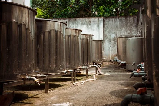
Selecting between membrane and thermal technologies requires a multi-parameter evaluation of energy consumption, which ranges from 0.1 kWh/m³ for capacitive deionization to over 20 kWh/m³ for multi-stage flash evaporation. While MBR is indispensable for removing organic contaminants (95% COD removal), its ability to reduce TDS is limited to approximately 30%, largely through biological uptake. Therefore, MBR serves as the ideal pretreatment for high-salinity streams but cannot achieve discharge compliance alone.
Capacitive Deionization (CDI) has emerged as the most cost-effective solution for "brackish" ranges (TDS 2,000–5,000 mg/L). CDI avoids the high pressure and membrane fouling associated with RO, though it is ineffective against non-ionic organic loads. Conversely, Reverse Osmosis (RO) provides high TDS removal (99%) but suffers from rapid fouling in etching wastewater treatment solutions for IC fabs due to the presence of silica and fluoride. The hybrid approach—using CDI to handle the bulk of the salinity and evaporation only for the final 5% of the volume—optimizes the energy-to-recovery ratio.
| Criteria | MBR | CDI | RO | Evaporation (MVR) |
|---|---|---|---|---|
| TDS Removal | Low (20-30%) | High (80-90%) | Very High (99%) | Absolute (99.9%) |
| Energy (kWh/m³) | 0.5 – 1.0 | 0.1 – 0.3 | 2.0 – 4.0 | 10 – 25 |
| CAPEX ($/m³) | $300 – $500 | $500 – $1,000 | $800 – $1,500 | $2,000 – $3,000 |
| Fouling Risk | Moderate | Low | High | Very Low (Scaling) |
| Salt Recovery | None | Brine only | Brine only | Solid Crystals |
The synergy of a hybrid MBR + CDI + Evaporation system allows fabs to bypass the limitations of standalone RO. By utilizing CDI for the intermediate salinity reduction, the volume of water requiring energy-intensive thermal evaporation is reduced by 80%, significantly lowering the total operational cost (OPEX) while ensuring 99.9% salt recovery for the entire stream.
CAPEX and OPEX Breakdown for IC High-Salinity Wastewater ZLD Systems: 2026 Cost Data
The total capital expenditure (CAPEX) for a 500 m³/day hybrid ZLD system in a semiconductor environment typically averages $2.5 million, with membrane modules and thermal evaporators accounting for 60% of the equipment cost. Beyond the primary equipment, civil works, electrical integration, and commissioning represent 20–30% of the total budget. For fabs processing TMAH wastewater treatment for semiconductor fabs, additional specialized chemical dosing and safety sensors can increase the CAPEX by another 10%.
Operational expenditure (OPEX) is dominated by energy costs, which fluctuate based on the TDS concentration of the influent. In a hybrid system, energy costs are mitigated by the low-consumption CDI stage ($0.05–$0.15/m³). Chemical costs for pH adjustment and membrane cleaning add approximately $0.02–$0.08/m³, while membrane replacement cycles (typically 3–5 years for PVDF MBRs) contribute $0.05–$0.15/m³/year. Labor and routine maintenance for high-pressure pumps and evaporators generally account for 2–5% of the initial CAPEX annually.
| Cost Category | Annual Expense/Value | Notes |
|---|---|---|
| Total CAPEX | $2,500,000 | Equipment + Installation |
| Total OPEX (Annual) | $500,000 | Energy, Chem, Labor |
| Salt Recovery Savings | $300,000 | Na₂SO₄ sale @ $150/ton |
| Avoided Fines/Fees | $150,000 | Discharge tax + compliance |
| Payback Period | 5.5 Years | Calculated on net savings |
To optimize ROI, fabs are increasingly integrating solar thermal arrays to pre-heat evaporation feed water and implementing automated membrane cleaning protocols to extend the lifespan of MBR and CDI components. the sale of recovered sodium sulfate at market prices ($100–$200/ton) provides a consistent revenue stream that can offset up to 40% of the system's annual OPEX.
Equipment Selection Framework: How to Choose the Right System for Your IC Fab
Engineering teams must follow a rigorous seven-step selection framework to mitigate the risks of membrane fouling and electrode scaling when treating complex semiconductor wastewater. The first step involves precise wastewater characterization using conductivity meters and COD digesters to determine the exact ionic composition and organic load. This data dictates whether the fab requires a biological pretreatment stage (MBR) or if it can proceed directly to deionization.
- Characterize Wastewater: Identify TDS, COD, pH, and specific ions (Fluoride, Ammonia, TMAH) through 24-hour composite sampling.
- Define Compliance Goals: Determine if the target is simple discharge compliance (GB 31573-2015) or full salt recovery and water reuse.
- Select Pretreatment: Implement GX Series rotary mechanical bar screens to remove slurry particles and automated dosing for pH stabilization.
- Choose Biological Stage: If COD > 1,000 mg/L, integrate a PVDF flat-sheet MBR to prevent organic fouling of downstream membranes.
- Size Deionization: Use CDI for TDS levels between 2,000 and 5,000 mg/L to minimize energy use; use RO only for extremely high-volume, low-organic streams.
- Add Thermal ZLD: Select MVR evaporation for the final brine concentration to achieve solid salt recovery and 100% water reclamation.
- Pilot Testing: Run a 1–5 m³/day pilot system for 3–6 months to establish cleaning frequencies and verify salt purity levels.
This framework ensures that the selected equipment—from the initial fine screening for IC fab wastewater pretreatment to the final crystallization unit—is sized correctly for the specific chemistry of the fab's production lines. Pilot testing is particularly vital for IC fabs, as the specific mixture of photoresists and etching acids can vary significantly between 28nm and 7nm process nodes.
Frequently Asked Questions
Q: What is the maximum TDS level that CDI can handle effectively?
A: CDI is most energy-efficient for TDS levels between 2,000 and 5,000 mg/L. While it can handle higher concentrations, the energy use increases, making RO or evaporation more competitive above 5,000 mg/L. CDI energy use is typically 0.1–0.3 kWh/m³ compared to 2–4 kWh/m³ for RO in this range.
Q: How does high salinity inhibit biological treatment in MBRs?
A: High inorganic salt concentrations increase environmental osmotic pressure, which can dehydrate microbial cells. This typically reduces COD removal efficiency by 30–50% if TDS exceeds 10,000 mg/L. Using salt-tolerant bacteria and maintaining high MLSS (8,000+ mg/L) in the MBR helps mitigate this inhibition.
Q: What is the typical payback period for a hybrid ZLD system in an IC fab?
A: For a 500 m³/day system, the payback period is usually 5–7 years. This is driven by savings from salt recovery (up to $0.3M/year), reduced water procurement costs, and the avoidance of high discharge fines and environmental taxes.
Q: Can recovered salts from IC wastewater be reused in manufacturing?
A: Yes. Sodium sulfate (Na₂SO₄) and sodium chloride (NaCl) recovered via MVR evaporation can achieve 99%+ purity. These are sold as industrial-grade raw materials for chemical manufacturing, glass production, or road de-icing, with market prices ranging from $100 to $200 per ton.
Q: What are the key maintenance challenges for CDI systems?
A: The primary challenges are electrode fouling from organic matter and mineral scaling. These are managed through regular automated cleaning cycles using mild acidic or alkaline solutions, high-quality pre-filtration (MBR), and periodic electrode regeneration protocols.