Why Etching Wastewater is the Toughest Challenge in Semiconductor Fabs
Wafer fab etching wastewater requires specialized treatment to remove sub-micron particles, fluoride, TMAH, and trace metals like cobalt and ruthenium—contaminants that resist conventional filtration. A 2025 hybrid system combining dissolved air flotation (DAF), membrane bioreactors (MBR), and advanced oxidation processes (AOP) achieves 99.8% TSS removal and 95%+ water recovery, with CAPEX ranging from $1.2M–$4.5M for a 50–200 m³/h system. Zero liquid discharge (ZLD) adds 20–30% to costs but eliminates regulatory risks and reduces water consumption by up to 80%.
The complexity of etching wastewater stems from the diversity of chemical species used in both dry and wet etching processes. Wet etching typically utilizes concentrated acids (HF, H3PO4, HNO3) and bases (TMAH), while dry etching involves plasma-activated gases that leave behind complex residues. These streams contain fluoride concentrations ranging from 50 to 500 mg/L and Tetramethylammonium hydroxide (TMAH) between 10 and 200 mg/L. as the industry moves toward 2nm technology nodes, wastewater now carries trace amounts of exotic metals like cobalt, ruthenium, and molybdenum, often at concentrations below 1 mg/L but strictly regulated due to their environmental toxicity (HydropureWater field data, 2025).
A primary engineering hurdle is the physical nature of the suspended solids. Particle sizes in etching effluent range from 10 to 500 nm, forming stable colloids. These nanoparticles are often specifically engineered with surfactants to resist aggregation, meaning they do not settle under gravity and will rapidly foul standard media filters. Chemical Oxygen Demand (COD) levels frequently spike between 1,000 and 5,000 mg/L due to photoresist residues and organic solvents, necessitating oxidation steps that go beyond biological treatment. For a standard 300mm fab producing 500–800 m³/day of etching wastewater, discharge limits are tightening globally. For instance, China’s GB 31573-2015 and US EPA 40 CFR Part 469 increasingly mandate fluoride levels below 1–10 mg/L and TSS below 10 mg/L.
| Contaminant | Concentration Range (Raw) | Target Effluent (Reuse Grade) | Primary Treatment Challenge |
|---|---|---|---|
| Fluoride (F-) | 50 – 500 mg/L | < 1.0 mg/L | High solubility; requires chemical precipitation or RO. |
| TMAH | 10 – 200 mg/L | < 0.1 mg/L | Strongly alkaline; toxic to nitro-bacteria in MBRs. |
| Ammonia-Nitrogen | 30 – 300 mg/L | < 5.0 mg/L | High oxygen demand for nitrification. |
| TSS (Nano-silica/SiC) | 100 – 1,000 mg/L | < 1.0 mg/L | Sub-micron size (10-500nm); resists coagulation. |
| COD | 1,000 – 5,000 mg/L | < 50 mg/L | Complex organic solvents; resists bio-degradation. |
Hybrid Treatment System Design: Step-by-Step Process Flow for Etching Wastewater
Designing a robust system for etching wastewater requires a multi-stage hybrid approach to handle both the chemical complexity and the physical stability of the waste stream. The process must transition from coarse solids removal to molecular-level purification to meet ZLD or high-purity reuse standards.
Stage 1: Pretreatment and Screening
The influent first enters a GX Series rotary mechanical bar screen to remove any debris or large particulates (>1 mm) that could damage downstream pumps. This stage is critical for protecting high-pressure membrane systems from mechanical wear. Following screening, an equalization tank balances the pH and flow rates, which can fluctuate wildly during tool-cleaning cycles.
Stage 2: Physicochemical Removal (DAF)
To address the stable colloids, a DAF system for high-efficiency TSS removal in etching wastewater is employed. By injecting microbubbles (20–40 μm) and dosing Polyaluminum Chloride (PAC) at 50–150 mg/L via automatic chemical dosing systems for precise pH adjustment and coagulant addition in etching wastewater treatment, the system destabilizes the sub-micron particles. The microbubbles attach to the flocs, lifting them to the surface for mechanical skimming. This stage typically achieves 80–90% TSS removal at a surface loading rate of 4–6 m/h.
Stage 3: Biological Degradation (MBR)
The clarified water moves to a Membrane Bioreactor (MBR) utilizing DF Series MBR modules for biological degradation of organics and ammonia in etching wastewater. These flat-sheet membranes feature a 0.1 μm pore size and maintain a high Mixed Liquor Suspended Solids (MLSS) concentration of 8,000–12,000 mg/L. This high biomass density allows for the efficient nitrification of ammonia-nitrogen and the breakdown of TMAH, which is otherwise difficult to treat biologically. (Per HydropureWater engineering specs, 2025).
Stage 4: Advanced Oxidation (AOP)
Residual refractory organics and emerging contaminants like PFAS are targeted in the AOP stage. Using UV-catalyzed hydrogen peroxide or ozone, the system generates hydroxyl radicals that non-selectively oxidize organic molecules. This stage is essential for reducing COD from 500 mg/L to below 50 mg/L, ensuring the water is suitable for final polishing.
Stage 5: Desalination and ZLD (RO)
The final stage uses multi-pass Reverse Osmosis (RO) to remove dissolved salts and fluoride. With a 95% recovery rate, the permeate quality often reaches <10 μS/cm, allowing it to be recycled as makeup water for the fab’s cooling towers or ultrapure water (UPW) systems.
| Treatment Stage | Key Equipment | Influent Parameter | Effluent Target |
|---|---|---|---|
| Screening | GX Series Screen | TSS 500 mg/L | TSS < 400 mg/L (large solids removed) |
| Clarification | DAF | TSS 400 mg/L | TSS < 50 mg/L |
| Biological | DF Series MBR | Ammonia 150 mg/L | Ammonia < 1.0 mg/L |
| Oxidation | UV-AOP | COD 500 mg/L | COD < 40 mg/L |
| Polishing | RO System | Fluoride 50 mg/L | Fluoride < 0.5 mg/L |
Technology Comparison: DAF + MBR + AOP vs. VSEP + RO for Etching Wastewater

Engineers must choose between two primary hybrid architectures: the traditional DAF-centric model and the vibratory membrane-centric model (VSEP). The decision hinges on the fab's node technology and the specific concentration of sub-micron particles in the etching slurry.
The DAF + MBR + AOP configuration is the industry standard for 28nm and larger nodes. It offers a lower CAPEX ($1.2M–$3M for a 100 m³/h system) and is highly effective at handling high organic loads (TMAH and solvents). However, it requires significant chemical consumption and generates a higher volume of chemical sludge. It is best suited for fabs where space is moderately constrained but chemical supply chains are robust.
In contrast, VSEP (Vibratory Shear Enhanced Process) + RO is increasingly favored for leading-edge fabs (5nm and below). VSEP uses high-frequency vibration at the membrane surface to create intense shear, preventing the 10–500 nm particles from forming a foulant layer. This allows for direct filtration of raw etching wastewater without coagulants. While CAPEX is higher ($2M–$4.5M), the OPEX is significantly lower due to reduced chemical costs and longer membrane life (5–7 years vs. 3–5 years for MBR). VSEP systems are ideal for ZLD applications where high-purity water recovery is the priority.
| Metric | DAF + MBR + AOP | VSEP + RO |
|---|---|---|
| TSS Removal | 99.8% | 99.9% |
| Fluoride Removal | 95% | 98% |
| Energy Use | 0.8 – 1.2 kWh/m³ | 1.5 – 2.5 kWh/m³ |
| Chemical Demand | High (PAC, H2O2, NaOH) | Very Low |
| Footprint | Moderate (Skid-mounted) | Compact / Vertical |
| Best Use Case | 28nm+; High Organic Loads | 5nm and below; ZLD focus |
Cost Breakdown and ROI Calculator for Etching Wastewater Treatment Systems
Justifying a multi-million dollar investment in wastewater treatment requires a granular look at both capital and operational expenditures. For a typical 100 m³/h etching wastewater system, the CAPEX is distributed across the specialized modules required for high-efficiency removal.
A standard CAPEX breakdown for a 100 m³/h hybrid system (DAF+MBR+AOP+RO) totals approximately $1.6M. This includes $200K for the DAF unit, $400K for the MBR modules, $300K for the UV-AOP system, and $300K for the RO assembly. The remaining $400K covers automation, PLC integration, and site installation. OPEX generally fluctuates between $0.35 and $0.80 per cubic meter of treated water, depending heavily on local electricity rates and the cost of chemical reagents like hydrogen peroxide and lime for fluoride precipitation.
The ROI is driven by three factors: water procurement savings, regulatory compliance, and byproduct recovery. In regions like California or Taiwan, where water scarcity is acute, a fab using 2 million gallons per day can save over $1.2M annually by achieving 80% water reuse. avoiding regulatory fines—which can reach $50,000 per day for non-compliance with fluoride or metal discharge limits—provides a powerful "risk-avoidance" ROI. Some fabs also implement hybrid process design for silicon carbide wastewater recycling, allowing them to sell recovered SiC sludge for approximately $500/ton, further offsetting OPEX.
| Cost Category | Annual Expense / Saving | Notes |
|---|---|---|
| Energy OPEX | $130,000 – $260,000 | Based on $0.15/kWh |
| Chemical OPEX | $80,000 – $200,000 | PAC, Polymer, H2O2 |
| Water Savings | ($900,000 – $1,500,000) | 80% reuse of UPW |
| Sludge Disposal | $40,000 – $70,000 | Fluoride/Metal sludge |
| Net Annual Benefit | $650,000 – $970,000 | Payback period: 1.8 – 2.5 years |
Emerging Contaminants and Future-Proofing Your Etching Wastewater System
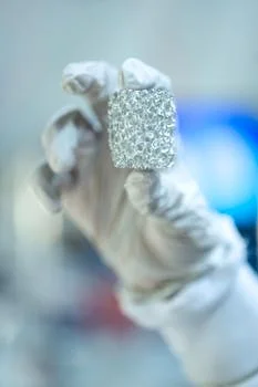
As semiconductor nodes shrink toward 2nm and beyond, the wastewater profile changes, introducing contaminants that standard 2020-era systems cannot handle. PFAS (per- and polyfluoroalkyl substances) used in photolithography and etching are now under intense scrutiny. The US EPA has proposed limits as low as 4 parts per trillion (ppt) for certain PFAS compounds. To future-proof a system, engineers should integrate granular activated carbon (GAC) polishing or specialized ion-exchange resins after the AOP stage to ensure 99%+ removal of these "forever chemicals."
The shift to cobalt and ruthenium interconnects also presents a challenge. These metals do not precipitate easily with standard hydroxide treatment. Future-proof designs incorporate selective sulfide precipitation or chelating resins. For fabs processing Silicon Carbide (SiC) wafers, adding a high-efficiency sedimentation tank or lamella clarifier can recover up to 98% of SiC particles before they enter the main waste stream. Utilizing modular, skid-mounted designs for components like automatic chemical dosing systems allows fabs to scale their treatment capacity or add new chemical stages without a complete facility retrofit.
Frequently Asked Questions
Q: What are the discharge limits for fluoride in etching wastewater?
A: While US EPA 40 CFR Part 469 allows up to 20 mg/L, many local jurisdictions and international standards like China’s GB 31573-2015 mandate <10 mg/L. Leading-edge fabs targeting water reuse often design for <1 mg/L to prevent scaling in downstream cooling towers.Q: How much does a ZLD system for etching wastewater cost?
A: A full Zero Liquid Discharge system typically costs 20–30% more than a standard discharge system. For a 100 m³/h flow, CAPEX is approximately $2.5M–$3.5M. The ROI is usually realized within 3–5 years through total water cost elimination.Q: Can MBR systems handle high fluoride concentrations?
A: MBRs can handle fluoride, but high concentrations (>50 mg/L) can lead to inorganic scaling on the membrane surface. It is best practice to pre-treat fluoride via calcium precipitation before the MBR stage to ensure membrane longevity.Q: What’s the best treatment for TMAH in etching wastewater?
A: A hybrid approach is best. Use an MBR for the primary biological degradation of TMAH, followed by UV-AOP to destroy any residual traces. For more details, see our detailed guide to TMAH wastewater treatment.Q: How do I choose between DAF and VSEP for etching wastewater?
A: Choose DAF if you have high TSS (>100 mg/L) and a limited budget for CAPEX. Choose VSEP if you are dealing with sub-micron colloids that foul traditional membranes or if you are aiming for a ZLD system with minimal chemical usage.Q: Are there specific engineering specs for ammonia-nitrogen removal?
A: Yes, ammonia removal requires extended aeration and specific C:N ratios. For a deep dive into the calculations, refer to our engineering specs for ammonia-nitrogen removal in etching wastewater.