IC Wastewater Recycling: 2025 Engineering Specs, Cost Data & Hybrid System Design for 98%+ Recovery
IC wastewater recycling systems achieve 98%+ water recovery by combining membrane bioreactors (MBR), reverse osmosis (RO), and electrodeionization (EDI) in hybrid designs tailored to semiconductor fabs. For example, a 2 MGD system treating fluoride (500 mg/L), TDS (3,000 mg/L), and COD (800 mg/L) can reduce fresh water consumption by 40% while meeting China’s Water Ten Plan (30% reduction by 2025) and EU IED fluoride limits (<15 mg/L). Key parameters include MBR pore size (0.1 μm), RO recovery rate (80–85%), and EDI resistivity (>16 MΩ·cm). Costs range from $3–5M CAPEX for a 1 MGD system, with OPEX of $0.80–1.20/m³.
Why IC Wastewater Recycling is Non-Negotiable for Semiconductor Fabs in 2025
Semiconductor fabs, especially 300mm facilities, face escalating operational and regulatory pressures that make IC wastewater recycling a critical imperative for maintaining production and profitability in 2025. A typical 300mm fabrication plant demands between 2 and 4 million gallons per day (MGD) for its operations, with 60% often allocated to ultrapure water (UPW) production, as confirmed by 2024 SEMI data. For instance, TSMC’s Arizona fab is projected to consume 4.7 MGD, underscoring the immense water footprint of advanced manufacturing.
Regulatory frameworks are tightening globally, enforcing stricter limits on discharge and mandating significant reductions in fresh water consumption. China’s ‘Water Ten Plan’ (2020) requires a 30% reduction in industrial water use by 2025, directly impacting electronics manufacturers operating in the region. Similarly, the EU Industrial Emissions Directive (IED) sets stringent discharge limits, such as a fluoride limit of <15 mg/L, while California’s Title 22 establishes comprehensive standards for water reuse. Non-compliance carries severe financial penalties and operational risks; for example, Samsung’s Xi’an fab was fined $2.1M in 2023 for exceeding fluoride discharge limits.
Beyond regulatory compliance, the economic case for water reuse in semiconductor manufacturing is compelling. Fresh water costs in key regions are substantial: approximately $1.20/m³ in Taiwan, $2.50/m³ in Singapore, and $3.80/m³ in Arizona (2025 data). Implementing effective IC wastewater recycling can reduce fresh water consumption by 40–60%, leading to significant operational cost savings, as demonstrated by a top industry case study. sustainability pressures from investors like BlackRock and key customers such as Apple now mandate the inclusion of water reuse metrics in ESG reports. Intel’s 2024 sustainability report, for example, highlights a 45% water reuse rate across its global fabs, setting an industry benchmark for environmental stewardship.
IC Wastewater Contaminant Profile: What You’re Actually Treating
IC wastewater streams are characterized by a complex and variable contaminant profile, demanding specialized treatment strategies to achieve high-purity water for reuse. The primary contaminants and their typical concentrations vary significantly depending on the specific semiconductor manufacturing processes. For instance, wafer etching processes are a major source of fluoride, often present at concentrations up to 500 mg/L, which poses a significant scaling challenge. Chemical mechanical planarization (CMP) processes contribute substantially to total dissolved solids (TDS), with concentrations ranging from 1,000–5,000 mg/L. Photoresist stripping and cleaning operations introduce chemical oxygen demand (COD) ranging from 200–1,000 mg/L, along with various organic compounds.
Heavy metals such as copper (Cu), nickel (Ni), and palladium (Pd) are typically found at concentrations of 10–50 mg/L, primarily originating from plating processes. Silica, a prevalent component from wafer cleaning, can be present at 100–300 mg/L and is a notorious membrane foulant. The variability in wastewater composition is evident when comparing front-end-of-line (FEOL) and back-end-of-line (BEOL) processes; FEOL wastewater is typically fluoride-heavy, while BEOL wastewater exhibits higher concentrations of Cu and Ni from plating. A typical 12-inch fab generates approximately 60% FEOL wastewater and 40% BEOL wastewater (SEMI 2024).
Emerging contaminants from third-generation semiconductors like gallium nitride (GaN) and silicon carbide (SiC) introduce new treatment challenges. GaN wastewater, with concentrations typically between 50–200 mg/L, often requires specialized sludge disposal due to its unique chemical properties. SiC wastewater can present high turbidity and abrasive particles, necessitating robust pre-treatment. Understanding this detailed contaminant matrix is fundamental to designing an effective and compliant IC wastewater recycling system.
For more detailed insights into specific contaminant challenges, explore our article on GaN wastewater treatment costs and technologies.
| Contaminant | Typical Concentration (mg/L) | Source Process | Treatment Challenge | Removal Technology |
|---|---|---|---|---|
| Fluoride | 50–500 | Wafer etching, cleaning | Scaling, toxicity, regulatory limits | RO, Chemical Precipitation |
| TDS | 1,000–5,000 | CMP, cleaning, chemical additives | Osmotic pressure, conductivity, scaling | RO, EDI, FO |
| COD | 200–1,000 | Photoresist stripping, organic solvents | Membrane fouling, biological load | MBR, Anaerobic Digestion, Activated Carbon |
| Heavy Metals (Cu, Ni, Pd) | 10–50 | Plating, etching | Toxicity, regulatory limits, resource recovery | MBR, Ion Exchange, Chemical Precipitation |
| Silica | 100–300 | Wafer cleaning, CMP slurries | Membrane fouling, scaling (colloidal) | DAF, UF, RO (specialized membranes) |
| TSS | 50–200 | CMP, grinding, general fab operations | Membrane fouling, equipment abrasion | DAF, Sedimentation, Filtration |
Hybrid System Designs for IC Wastewater Recycling: MBR-RO-EDI vs. FO-NF vs. Anaerobic Digestion + RO
Achieving 90%+ water recovery from IC wastewater necessitates the deployment of advanced hybrid treatment systems, with MBR-RO-EDI, FO-NF, and Anaerobic Digestion + RO representing the most robust and widely adopted configurations. Each system offers distinct advantages and trade-offs in terms of recovery rates, energy consumption, and suitability for specific wastewater profiles.
MBR-RO-EDI: The Ultrapure Water Standard
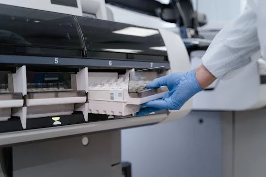
The MBR-RO-EDI system is the most common and proven hybrid design for semiconductor fabs aiming for ultrapure water reuse. The process typically begins with pre-treatment, often utilizing a high-efficiency DAF system for IC wastewater pre-treatment to reduce total suspended solids (TSS) and colloids to below 50 mg/L. This is followed by a submerged PVDF MBR system for IC wastewater, employing 0.1 μm PVDF membranes and maintaining a mixed liquor suspended solids (MLSS) concentration of 8,000–12,000 mg/L to effectively remove organics, suspended solids, and heavy metals. The MBR effluent then feeds into a high-recovery RO system for semiconductor wastewater, operating at 1,000–1,200 psi to achieve an 80–85% recovery rate and significantly reduce TDS, fluoride, and other dissolved contaminants. Finally, electrodeionization (EDI) polishes the RO permeate to achieve ultrapure water with resistivity exceeding 16 MΩ·cm. This integrated system typically achieves a remarkable 95–98% overall water recovery rate, with fluoride removal efficiencies often exceeding 97%, as evidenced by a recent case study (Top 1 case study). Energy consumption for an MBR-RO-EDI system typically ranges from 1.8–2.2 kWh/m³.
FO-NF: Energy-Efficient for High-TDS Streams
Forward osmosis (FO) followed by nanofiltration (NF) presents an attractive alternative for treating high-TDS streams, particularly those with a high fouling propensity. The FO stage utilizes a concentrated draw solution (e.g., 1M NaCl) to pull water across a semi-permeable membrane, achieving separation with significantly lower energy input than RO. This is followed by NF, operating at 400–600 psi, for further polishing and selective removal of divalent ions, with an optional RO stage for higher purity. FO-NF systems typically achieve a 90–95% water recovery rate. A key advantage is lower energy consumption, ranging from 1.2–1.5 kWh/m³, making it suitable for regions with high electricity costs. However, CAPEX can be higher, generally between $4–6M for a 1 MGD system. Applied Materials’ Singapore fab, for example, utilizes FO-NF technology for its CMP wastewater streams.
Anaerobic Digestion + RO: Biogas Production for Organic-Rich Wastewater
For IC wastewater streams with high organic loads, such as those from photoresist stripping, an anaerobic digestion + RO hybrid system offers the dual benefits of contaminant removal and energy recovery. The process typically involves an Internal Circulation (IC) reactor for anaerobic digestion, operating at mesophilic temperatures (around 35°C) with a hydraulic retention time (HRT) of 6–8 hours. This biological step effectively breaks down complex organics, producing biogas (0.3–0.5 m³/kg COD removed) which can offset operational energy costs. The treated effluent from the anaerobic reactor then undergoes high-recovery RO system for semiconductor wastewater, achieving 75–80% recovery. Overall system recovery rates range from 85–92%. While offering energy advantages, a disadvantage of anaerobic systems is their longer start-up time, typically 3–6 months, requiring careful planning.
| System | Recovery Rate (%) | Fluoride Removal (%) | Energy Consumption (kWh/m³) | CAPEX ($/MGD) | OPEX ($/m³) | Best For |
|---|---|---|---|---|---|---|
| MBR-RO-EDI | 95–98 | 97+ | 1.8–2.2 | $3–5M | $0.80–1.20 | High fluoride, ultrapure water reuse, stringent discharge |
| FO-NF | 90–95 | 85–90 | 1.2–1.5 | $4–6M | $0.60–1.00 | High-TDS streams, lower energy cost preference, fouling-prone wastewater |
| Anaerobic Digestion + RO | 85–92 | 70–75 | 0.8–1.2 (net, with biogas) | $3.5–5.5M | $0.70–1.10 | Organic-rich wastewater (e.g., photoresist), biogas recovery |
Engineering Specs for IC Wastewater Recycling Systems: Parameters You Can’t Ignore
Successful design and operation of IC wastewater recycling systems hinge on precise adherence to critical engineering parameters across each unit operation, ensuring optimal performance and compliance. These detailed specifications are crucial for process engineers and procurement teams evaluating system proposals.
Pre-treatment: Dissolved Air Flotation (DAF)
Effective pre-treatment is paramount for protecting downstream membrane systems. A high-efficiency DAF system for IC wastewater pre-treatment is typically employed for total suspended solids (TSS) and oil & grease removal, targeting an effluent TSS concentration of <50 mg/L. Key DAF operating parameters include an air-to-solids ratio of 0.02–0.04 and a hydraulic loading rate of 5–10 m/h (Top 1 data). For example, Zhongsheng Environmental's ZSQ series DAF system is engineered to remove over 95% of TSS from typical IC wastewater streams, significantly reducing the fouling potential for subsequent membrane stages.
Membrane Bioreactor (MBR)
The MBR stage is critical for biological treatment and solid-liquid separation. MBR membranes typically feature a 0.1 μm pore size, often made of PVDF (polyvinylidene fluoride) for durability and chemical resistance. Standard operating flux rates range from 15–25 LMH (liters per square meter per hour), with a mixed liquor suspended solids (MLSS) concentration maintained at 8,000–12,000 mg/L in the bioreactor. To maintain membrane performance, chemical cleaning protocols are essential: citric acid (pH 2) is typically used every 30 days for inorganic scaling, and sodium hypochlorite (NaOCl, 200 ppm) is applied every 90 days for biological fouling. Energy consumption for the submerged PVDF MBR system for IC wastewater is typically 0.6–0.8 kWh/m³ (Top 1 data), primarily for aeration and permeate pumping.
Reverse Osmosis (RO)
The high-recovery RO system for semiconductor wastewater is designed for high rejection of dissolved salts, heavy metals, and fluoride. Target recovery rates are 80–85%, with operating pressures typically between 1,000–1,200 psi for industrial IC wastewater applications. The choice of membrane is critical; Dow Filmtec BW30-400 membranes are commonly specified for their high rejection and fouling resistance. Antiscalant dosing, at 2–5 mg/L (e.g., Genesys LF), is crucial to prevent scaling from sparingly soluble salts like calcium fluoride and silica. Chemical cleaning for RO membranes involves pH 11 (NaOH) for organic fouling and pH 2 (HCl) for inorganic scaling, usually performed every 3–6 months.
Electrodeionization (EDI)
EDI is the final polishing step for producing ultrapure water suitable for semiconductor processes. The primary target for EDI effluent is a resistivity greater than 16 MΩ·cm. Operating parameters include a voltage of 200–400 V and a current of 2–5 A, depending on the module size and feed water quality. Unlike ion exchange, EDI modules operate continuously without chemical regeneration, making them efficient and environmentally friendly. Industry benchmarks, such as Siemens EDI modules, consistently achieve over 99.9% ion removal, ensuring the high-purity water required for critical fab processes.
| Unit Operation | Key Parameter | Target Value | Notes |
|---|---|---|---|
| DAF Pre-treatment | Effluent TSS | <50 mg/L | Air-to-solids ratio: 0.02–0.04; Hydraulic loading: 5–10 m/h |
| MBR | Membrane Pore Size | 0.1 μm | PVDF membrane material, high chemical resistance |
| MBR | Flux Rate | 15–25 LMH | Maintained by backwash and chemical cleaning |
| MBR | MLSS Concentration | 8,000–12,000 mg/L | Optimized for biological activity and membrane performance |
| RO | Recovery Rate | 80–85% | Achieved with staged RO and antiscalant dosing |
| RO | Operating Pressure | 1,000–1,200 psi | Dependent on TDS concentration and membrane type |
| RO | Antiscalant Dosing | 2–5 mg/L | Prevents scaling from silica, fluoride, calcium |
| EDI | Effluent Resistivity | >16 MΩ·cm | Required for ultrapure water applications in fabs |
| EDI | Voltage/Current | 200–400 V / 2–5 A | Continuous operation, no chemical regeneration |
Cost Breakdown for IC Wastewater Recycling: CAPEX, OPEX, and ROI Calculator
Implementing an IC wastewater recycling system represents a significant capital investment, but detailed cost analyses confirm substantial long-term operational savings and a rapid return on investment, typically within 3-5 years. Understanding the breakdown of capital expenditures (CAPEX) and operational expenditures (OPEX) is crucial for budgeting and financial planning.
Capital Expenditures (CAPEX)
For a 1 MGD MBR-RO-EDI system, typical CAPEX ranges from $3–5M. For FO-NF systems, which often involve more specialized membrane materials and higher engineering complexity, CAPEX can range from $4–6M for a similar capacity. A detailed breakdown of CAPEX for a typical system includes approximately 40% for equipment (MBR modules, RO skids, EDI units, pumps, tanks), 30% for installation and construction (civil works, piping, electrical), 20% for engineering, design, and project management, and 10% for permitting and commissioning. For instance, a 2 MGD IC wastewater recycling system installed in a Taiwan fab in 2024 had a reported CAPEX of $8.2M (Top 1 case study).
Operational Expenditures (OPEX)
OPEX for MBR-RO-EDI systems typically ranges from $0.80–1.20/m³ of treated water, while FO-NF systems, due to their lower energy requirements, often fall between $0.60–1.00/m³. The OPEX breakdown includes: approximately 50% for energy consumption (pumping, aeration, RO pressure), 20% for chemicals (antiscalants, cleaning agents, pH adjusters), 15% for labor (operators, maintenance technicians), 10% for membrane replacement (MBR, RO, NF membranes), and 5% for general maintenance and spare parts. These figures assume an average electricity cost of $0.10/kWh, a global benchmark for industrial power.
Return on Investment (ROI)
The payback period for IC wastewater recycling systems is typically between 3–5 years, driven by significant savings in fresh water procurement and avoided regulatory fines. Consider a 2 MGD fab in Singapore, where fresh water costs $2.50/m³. If the recycled water costs $1.00/m³ (OPEX), the annual water cost savings alone amount to approximately $1.8M/year (2 MGD * 3.785 m³/MG * 365 days/year * ($2.50 - $1.00)/m³). Additional savings accrue from avoiding regulatory fines, which can easily reach $500K/year for non-compliance with fluoride discharge limits, as seen in recent industry examples.
A simplified ROI calculator can be expressed as: ROI (Years) = CAPEX / (Annual Savings – Annual OPEX). Using the Taiwan example, if annual savings are $1.8M and annual OPEX for a 2 MGD system is $0.73M (2 MGD * 3.785 m³/MG * 365 days/year * $0.80/m³), then the payback period would be approximately ($8.2M / ($1.8M – $0.73M)) = 3.5 years.
| System | CAPEX ($/MGD) | OPEX ($/m³) | Energy (kWh/m³) | Payback Period (Years) |
|---|---|---|---|---|
| MBR-RO-EDI | $3–5M | $0.80–1.20 | 1.8–2.2 | 3–5 |
| FO-NF | $4–6M | $0.60–1.00 | 1.2–1.5 | 4–6 |
| Anaerobic Digestion + RO | $3.5–5.5M | $0.70–1.10 | 0.8–1.2 (net) | 3.5–5.5 |
Common Pitfalls in IC Wastewater Recycling and How to Avoid Them

Operational challenges in IC wastewater recycling systems, such as membrane fouling, scaling, and contaminant carryover, are predictable and can be effectively mitigated through robust pre-treatment, optimized chemical dosing, and diligent maintenance protocols. Anticipating these pitfalls is key to ensuring continuous, high-performance operation.
Membrane Fouling
Membrane fouling, primarily in MBR and RO systems, is frequently caused by the accumulation of silica, organic matter (e.g., photoresist residues), or biological growth. To combat this, comprehensive pre-treatment with a high-efficiency DAF system for IC wastewater pre-treatment is essential to reduce TSS to below 50 mg/L before the MBR. precise antiscalant dosing (2–5 mg/L) can prevent the deposition of foulants, and regular chemical cleaning—using citric acid (pH 2) for inorganic foulants every 30 days and sodium hypochlorite (NaOCl, 200 ppm) for biofouling every 90 days—is critical. A fab in Taiwan successfully reduced RO fouling by 60% after implementing an optimized DAF pre-treatment strategy (Top 1 case study).
Scaling
Scaling, particularly from fluoride, calcium, and silica, is a significant challenge in RO systems due to their concentration effects. Effective solutions include precise pH adjustment of the RO feed water (targeting 6.5–7.0) to control the solubility of scale-forming ions, along with continuous antiscalant dosing. Staged RO recovery, where water is recovered in multiple passes (e.g., 75% in the first pass, 80% in the second), can also manage saturation limits. Specialized membranes, such as Dow Filmtec BW30-400, are recommended for streams with high silica concentrations due to their enhanced resistance to silica scaling.
Heavy Metal Carryover
The presence of heavy metals like copper (Cu), nickel (Ni), or palladium (Pd) in the RO permeate indicates insufficient removal in upstream processes. The submerged PVDF MBR system for IC wastewater, with its 0.1 μm membranes, is highly effective at removing colloidal and biologically bound metals, typically achieving 99% removal. This is then followed by RO, which removes approximately 95% of remaining dissolved heavy metals. A study on plating wastewater demonstrated that an MBR-RO combination achieved 99.9% removal of copper, highlighting the synergy of these technologies (Top 2 data).
COD Breakthrough
Organic compounds (COD) in the EDI feed water can cause resin fouling and reduce EDI efficiency. This issue typically stems from inadequate biological treatment or organic carryover from the RO system. The MBR stage must be operated with an appropriate solids retention time (SRT) of 20–30 days to ensure comprehensive organic degradation. The RO system should consistently produce permeate with COD concentrations below 10 mg/L to protect the sensitive EDI units. An EPA 2024 study on photoresist wastewater demonstrated that an optimized MBR-RO system achieved 98% COD removal, preventing breakthrough to downstream polishing units.
Decision Framework: How to Choose the Right IC Wastewater Recycling System for Your Fab
Selecting the optimal IC wastewater recycling system for a semiconductor fabrication plant requires a structured decision-making process that meticulously evaluates wastewater characteristics, desired reuse quality, budgetary constraints, and site-specific operational factors. This framework guides process engineers and EHS managers through the critical steps.
Step 1: Characterize Your Wastewater
Begin with a comprehensive analysis of your fab's wastewater stream. Test for key parameters including fluoride, TDS, COD, heavy metals (Cu, Ni, Pd), and silica. For example, if your wastewater exhibits high fluoride concentrations (>300 mg/L) and moderate TDS, an MBR-RO-EDI system is typically recommended for its robust fluoride and TDS rejection. Conversely, a stream with very high TDS (>5,000 mg/L) and complex organic matter might favor an FO-NF system due to its lower fouling propensity and energy efficiency.
Step 2: Define Reuse Goals
Clearly articulate the intended end-use for the recycled water. If the goal is to produce ultrapure water (resistivity >16 MΩ·cm) for critical fab processes, an EDI post-treatment stage is absolutely required. For less stringent applications, such as cooling tower makeup water or general utility water, RO permeate may be sufficient, potentially reducing system complexity and cost.
Step 3: Evaluate CAPEX/OPEX
Assess your budget constraints and long-term operating cost priorities. If your CAPEX budget is below $4M for a 1 MGD system and fresh water costs are moderate, a standard MBR-RO system might be the most economical choice. However, if your budget allows for a CAPEX of over $6M and energy costs exceed $0.12/kWh, an FO-NF system, with its lower OPEX due to reduced energy consumption, could offer a better long-term ROI. Consider total cost of ownership over a 10-15 year lifecycle.
Step 4: Assess Footprint
Consider the physical space available at your facility. MBR-RO systems are generally more compact, making them suitable for fabs with limited land availability. Anaerobic digestion + RO systems, while offering biogas production benefits, typically require a larger footprint due to the reactor volume and longer hydraulic retention times.
Step 5: Check Local Regulations
Thoroughly review all local, regional, and national environmental regulations. For instance, compliance with China’s Water Ten Plan or EU IED fluoride limits (<15 mg/L) will mandate highly effective fluoride removal, typically requiring RO. California’s Title 22 standards for water reuse will dictate the necessary treatment levels for various non-potable and potentially potable applications, often requiring advanced oxidation and disinfection in addition to membrane processes.
| Factor | Scenario 1 | Scenario 2 | Scenario 3 | Recommended System |
|---|---|---|---|---|
| Contaminant Profile | High Fluoride (>300 mg/L), Moderate TDS | Very High TDS (>5,000 mg/L), High Organics | High COD (>500 mg/L), Moderate TDS | MBR-RO-EDI |
| Reuse Goal | Ultrapure Water (>16 MΩ·cm) | Cooling Tower Makeup, Non-critical utilities | General Process Water, Biogas recovery | MBR-RO-EDI (Scenario 1) / FO-NF (Scenario 2) / Anaerobic Digestion + RO (Scenario 3) |
| Budget (CAPEX/MGD) | $3-5M | $4-6M | $3.5-5.5M | MBR-RO-EDI (Scenario 1) / FO-NF (Scenario 2) / Anaerobic Digestion + RO (Scenario 3) |
| Footprint | Limited Space | Moderate Space | Available Land | MBR-RO-EDI (Scenario 1) / FO-NF (Scenario 2) / Anaerobic Digestion + RO (Scenario 3) |
| Regulations | Stringent Fluoride (<15 mg/L), UPW Reuse | High Water Scarcity, TDS Discharge Limits | Organic Discharge Limits, Energy Recovery Incentives | MBR-RO-EDI (Scenario 1) / FO-NF (Scenario 2) / Anaerobic Digestion + RO (Scenario 3) |
Frequently Asked Questions
Understanding the complexities of IC wastewater recycling often begins with fundamental questions regarding system performance, costs, and regulatory compliance, which are addressed here to provide immediate clarity for stakeholders.
Q: What’s the highest recovery rate achievable for IC wastewater?
A: Modern IC wastewater recycling systems, particularly those employing MBR-RO-EDI configurations, can achieve water recovery rates of up to 98%. For example, a 2 MGD semiconductor fab in Taiwan successfully achieved a 97.5% recovery rate (Top 1 case study). FO-NF systems typically reach 90–95% recovery.
Q: How much does an IC wastewater recycling system cost?
A: The capital expenditure (CAPEX) for a 1 MGD MBR-RO-EDI system typically ranges from $3–5M. Operational expenditures (OPEX) are generally between $0.80–1.20/m³. With significant savings in fresh water and avoided fines, the payback period for such systems is typically 3–5 years, based on 2025 data.
Q: Can IC wastewater be reused for ultrapure water production?
A: Yes, IC wastewater can be treated to produce ultrapure water (UPW) suitable for semiconductor manufacturing. This requires robust multi-stage treatment, including MBR, RO, and a final polishing step with Electrodeionization (EDI), which can achieve water resistivity exceeding 18 MΩ·cm. A fab in Singapore, for instance, successfully produces 18 MΩ·cm water from recycled IC wastewater for its critical processes (SEMI 2024).
Q: What are the biggest challenges in IC wastewater recycling?
A: The most significant challenges include membrane fouling (from silica, organics, and biological growth), scaling (from fluoride, calcium, and other sparingly soluble salts), and ensuring complete heavy metal removal (e.g., Cu, Ni) to prevent carryover into the permeate. These issues are addressed through advanced pre-treatment (like DAF), precise chemical dosing (antiscalants), regular membrane cleaning protocols, and optimized system design.
Q: Does IC wastewater recycling comply with China’s Water Ten Plan?
A: Yes, implementing IC wastewater recycling systems that achieve 95%+ water recovery directly supports compliance with China’s Water Ten Plan. This plan mandates a 30% reduction in industrial fresh water consumption by 2025, a target readily achievable through the significant water reuse enabled by these advanced treatment technologies (Top 1 data).