A multi media filter (MMF) is a depth filtration system designed to remove suspended solids, turbidity, and colloidal matter from industrial water, achieving effluent quality in the 10-20 micron range. Typical specifications include a 30-48 inch bed depth with 5 layers: anthracite (.8-.9 mm) for coarse filtration, sand (.45-.55 mm) for intermediate particles, and garnet (#8-12 and #30-40) for fine solids, supported by gravel (1/4" x 1/8"). Service flow rates range from 12-20 gpm/sq. ft., with backwash rates of 13-18 gpm/sq. ft. to prevent media compaction. These filters reduce SDI (Silt Density Index) to <3, protecting downstream RO systems requiring low-SDI pre-treatment from fouling.
Why Multi Media Filters Fail: A Plant Manager’s Problem with RO Fouling
Poorly designed multi media filters are the primary cause of premature Reverse Osmosis (RO) membrane failure, often resulting in a 30-50% reduction in membrane service life. In a recent case study, a food processing plant in Malaysia experienced a 40% increase in RO membrane fouling within six months of commissioning. Despite having an MMF in place, the Silt Density Index (SDI) consistently exceeded 5.0, far above the required <3.0 threshold. Investigation revealed that the filter was undersized for the peak influent turbidity and utilized an incorrect media layering sequence that lacked the fine garnet layers necessary for polishing.
The cost of such failures is significant. Beyond the immediate expense of membrane replacement—which can range from $5,000 to $50,000 per event depending on system size—plants face substantial downtime, often 24 to 72 hours, and increased chemical consumption for Clean-In-Place (CIP) procedures. Common technical causes of failure include media mixing due to improper backwash rates, channeling where water bypasses the media bed, and inadequate bed depth which allows for particle breakthrough.
To avoid these outcomes, engineers must adhere to precise RO water treatment specifications and pre-treatment requirements. Properly specified multi media filters utilize progressive density filtration to trap particles throughout the entire bed depth rather than just at the surface. This design ensures that SDI is maintained <3, effectively extending the lifecycle of downstream membranes and reducing the total cost of ownership for the facility.
Multi Media Filter Specifications: Bed Depth, Media Layers, and Particle Removal
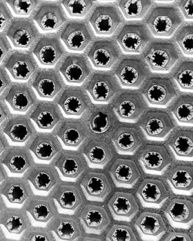
Industrial multi media filters achieve superior filtration by utilizing a 30-48 inch bed depth comprised of at least five distinct layers of varying density and size. Unlike single-media sand filters that trap solids only in the top 2-3 inches, MMF systems distribute the solids load throughout the entire depth of the bed. Shallower beds (less than 30 inches) risk immediate breakthrough during flow surges, while beds exceeding 48 inches create excessive pressure drop and require higher energy consumption for backwashing without providing proportional gains in water quality.
The media layers are arranged from least dense (top) to most dense (bottom). This ensures that during backwash, the layers resettle in the correct order. The top layer consists of anthracite coal (.8-.9 mm), which captures coarse particles (50-100 microns). Below this is a layer of fine filter sand (.45-.55 mm) for intermediate particles (20-50 microns). The final polishing occurs in the garnet layers (#30-40 and #8-12), which remove fine solids down to 10-20 microns. The entire stack is supported by a gravel base (1/4" x 1/8") that prevents media migration into the underdrain system.
| Media Layer | Effective Size (mm) | Density (lbs/cu. ft.) | Removal Range (Microns) | Function in Bed |
|---|---|---|---|---|
| Anthracite | 0.8 - 0.9 | 50 | 50 - 100 | Primary coarse solids capture |
| Filter Sand | 0.45 - 0.55 | 100 | 20 - 50 | Intermediate particle removal |
| Garnet #30-40 | 0.35 - 0.45 | 130 | 10 - 20 | Fine particle polishing |
| Garnet #8-12 | 1.5 - 2.0 | 140 | Pre-support | Transition to support bed |
| Support Gravel | 3.0 - 6.0 | 100 | N/A | Flow distribution/Underdrain protection |
The Zhongsheng Environmental multi-media filters for industrial water treatment leverage this 5-layer configuration to maximize solids-holding capacity. Water flows downward through progressively finer media, with solids trapped in the interstitial spaces. This depth filtration mechanism allows for longer run times between backwash cycles compared to surface filtration methods.
Flow Rates, Backwash, and Pressure Drop: Design Parameters for Industrial Applications
Standard service flow rates for industrial multi media filters typically range from 12 to 20 gpm/sq. ft., depending on the variability of influent water quality. In applications with high Total Suspended Solids (TSS) or fluctuating turbidity, engineers should design for the lower end of this range (12 gpm/sq. ft.) to prevent premature media compaction and ensure consistent effluent quality. Operating above 20 gpm/sq. ft. significantly increases the risk of "breakthrough," where particles are forced through the media bed by hydraulic pressure.
Backwash performance is the most critical factor in maintaining filter longevity. A backwash rate of 13-18 gpm/sq. ft. is required to achieve a 30-50% bed expansion. This expansion is necessary to release trapped particles and re-stratify the media layers. If the backwash rate is too low, the bed remains compacted, leading to "mud balling" and channeling. If it is too high, media may be washed out of the vessel and lost to the drain. Backwash cycles typically last 10-15 minutes and are triggered either by a timer (once every 24 hours) or by a differential pressure (DP) setpoint.
| Parameter | Typical Range | Design Limit/Setpoint | Impact of Deviation |
|---|---|---|---|
| Service Flow Rate | 12 - 20 gpm/sq. ft. | Max 20 gpm/sq. ft. | High rates cause breakthrough/compaction |
| Backwash Flow Rate | 13 - 18 gpm/sq. ft. | 30-50% Bed Expansion | Low rates cause media mixing/fouling |
| Initial Pressure Drop | 1 - 3 psi | < 5 psi (Clean) | High clean DP indicates media issues |
| Terminal Pressure Drop | 8 - 12 psi | Max 15 psi | Exceeding 15 psi risks vessel/media damage |
| Backwash Duration | 10 - 15 minutes | Until clear | Short cycles leave solids in the bed |
Monitoring pressure drop across the bed is essential for operational health. A clean filter bed typically exhibits an initial pressure drop of 1-3 psi. As solids accumulate, the pressure drop increases. Per industrial standards (Zhongsheng field data, 2025), a filter must be backwashed when the differential pressure reaches 8-10 psi. Allowing the pressure drop to exceed 15 psi can lead to media crushing or structural damage to the internal lateral distributors.
Multi Media Filter Design Calculations: How to Size a Filter for Your Water Quality
Sizing a multi media filter requires a systematic approach based on the peak flow rate and the specific solids loading of the influent water. For a textile plant requiring 300 gpm of process water with an influent TSS of 100 mg/L, the sizing process follows these engineering steps:
Step 1: Determine Required Filtration Area. Using a conservative design flux of 12 gpm/sq. ft. to account for the high TSS:
Area = Flow Rate / Flux = 300 gpm / 12 gpm/sq. ft. = 25 sq. ft.
Step 2: Select Vessel Configuration. A single 72-inch diameter vessel provides approximately 28.3 sq. ft. of area. Alternatively, two 48-inch vessels (12.6 sq. ft. each) in parallel provide 25.2 sq. ft. Parallel configurations are often preferred for continuous operation, allowing one unit to backwash while the other remains in service.
Step 3: Calculate Media Volume. Based on a standard 42-inch (3.5 ft) bed depth for the 25 sq. ft. area:
Total Volume = 25 sq. ft. × 3.5 ft. = 87.5 cu. ft.
Step 4: Determine Media Weights (Based on 5-layer Standard).
- Anthracite (20% of bed): 17.5 cu. ft. × 50 lbs/cu. ft. = 875 lbs
- Filter Sand (30% of bed): 26.25 cu. ft. × 100 lbs/cu. ft. = 2,625 lbs
- Garnet #30-40 (20% of bed): 17.5 cu. ft. × 130 lbs/cu. ft. = 2,275 lbs
- Garnet #8-12 (15% of bed): 13.1 cu. ft. × 140 lbs/cu. ft. = 1,834 lbs
- Gravel Support (15% of bed): 13.1 cu. ft. × 100 lbs/cu. ft. = 1,310 lbs
For high-capacity requirements, Zhongsheng Environmental multi-media filters for industrial water treatment provide customized sizing to ensure that even under peak loading, the velocity remains within safe design limits to prevent media migration.
Media Layer Configurations: Which Setup Works Best for Your Contaminants?

While the standard 5-layer configuration is the industry benchmark for general turbidity removal, specific industrial contaminants require modified media blends to achieve optimal effluent quality. For example, municipal water pre-treatment often utilizes a 4-layer configuration (omitting the coarse anthracite) because the influent TSS is typically below 30 mg/L, making the coarse filtration stage redundant.
In contrast, heavy industrial applications dealing with iron or manganese must incorporate catalytic media such as manganese greensand or BIRM. These materials oxidize dissolved metals into solid particles that the subsequent layers can then trap. For food and beverage applications where oil and grease (FOG) are present, anthracite is often replaced with walnut shell media or activated carbon, which provides adsorption properties that standard MMF media lacks.
| Contaminant Challenge | Recommended Configuration | Performance Benchmark |
|---|---|---|
| High Turbidity (>100 NTU) | Deep-bed Anthracite (1.2-1.4 mm) + Standard MMF | 95-99% TSS Removal |
| Iron & Manganese | Manganese Greensand replacing Anthracite | <0.3 mg/L Iron Effluent |
| Oil & Grease (<20 mg/L) | Walnut Shell media top layer | 90% FOG Reduction |
| Fine Colloidal Silica | Extended Garnet #30-40 layer (12"+) | SDI < 2.5 |
| Cooling Tower Side-stream | Standard 5-Layer MMF | <5 NTU Turbidity |
Customizing the media blend allows for targeted removal. According to MECO field data, a 5-layer filter typically achieves 90-95% TSS removal, but a custom blend designed for specific particle size distributions can reach 99% efficiency. If heavy FOG or emulsified oils are present, engineers should consider DAF systems for high-FOG or emulsified contaminant removal as a primary treatment stage before the MMF.
Multi Media Filter vs. Alternatives: When to Use Depth Filtration vs. Cartridge, Bag, or Membrane Filters
Multi media filters are the preferred choice for high-flow industrial applications (50 to 10,000 gpm) where TSS levels range from 10 to 500 mg/L. Compared to cartridge or bag filters, MMF systems have a significantly higher initial capital cost but much lower ongoing operating expenses because the media is cleaned via backwash rather than replaced. Cartridge filters are generally reserved for low-flow polishing applications or as a final safety barrier immediately before an RO unit.
When effluent quality requirements are extremely stringent—such as for water reuse or ultrapure water—Ultrafiltration (UF) membranes may be necessary. UF achieves <0.1 micron removal, whereas MMF is limited to 10-20 microns. However, UF systems require significant pre-treatment to prevent membrane fouling, often using an MMF as the primary stage. For applications with extremely high solids or grease, a combination of DAF and MMF provides the most robust solution.
| Technology | Removal Rating | Best For... | Operating Cost |
|---|---|---|---|
| Multi Media Filter | 10 - 20 Microns | High flow, high TSS pre-treatment | Low (Backwashable) |
| Cartridge Filter | 1 - 5 Microns | Low flow, final polishing | High (Disposable) |
| Ultrafiltration (UF) | 0.01 - 0.1 Microns | Water reuse, virus removal | Medium (Chemical cleaning) |
| Bag Filter | 5 - 200 Microns | Batch processing, coarse solids | High (Disposable) |
Choosing the right technology depends on the lifecycle cost analysis. Procurement managers should evaluate the trade-off between the MMF's footprint and capital cost versus the high recurring labor and material costs of disposable filters. For advanced biological wastewater applications, engineers may also review MBR specifications for advanced wastewater treatment as a combined filtration and biological solution.
Troubleshooting Multi Media Filters: Common Problems and How to Fix Them
Operational issues in multi media filters often manifest as a sudden drop in effluent quality or a rapid increase in pressure drop. Media mixing is a common problem where the layers lose their stratification, typically caused by excessive backwash flow rates or air scour issues. If the anthracite and sand mix, the filter loses its depth-filtration capability and acts as a surface filter, leading to short run times and high head loss.
Channeling is another frequent issue, where the water carves a path through the media rather than flowing evenly across the bed. This is usually caused by a blocked underdrain lateral or a failed distributor. Channeling results in immediate turbidity breakthrough because the water is not being filtered by the media. Regular inspection of the internal components and the use of air scouring during backwash can prevent media compaction and channeling.
| Symptom | Probable Cause | Corrective Action |
|---|---|---|
| High SDI in Effluent | Media exhaustion or channeling | Perform extended backwash; check underdrains |
| Media in Effluent | Failed lateral or excessive backwash | Inspect internal screens; calibrate flow rates |
| Rapid DP Increase | High influent TSS or mud-balling | Increase backwash frequency; add air scour |
| Short Filter Runs | Surface blinding/Inadequate bed depth | Check anthracite layer depth; verify flux rate |
| Turbidity Breakthrough | Flow surges or incorrect media sizing | Install VFD on pumps; verify media specifications |
If the filter has been in operation for more than 3-5 years and effluent quality is declining despite proper backwashing, the media may be "spent" due to physical attrition or chemical scaling. In such cases, a full media replacement is required to restore performance to design specifications.
Selecting a Multi Media Filter: Decision Framework for Procurement Managers
Procurement managers must balance technical performance with long-term reliability when selecting an MMF system. The first step is defining the water quality baseline: a system designed for 50 NTU influent will fail if the actual source water fluctuates to 150 NTU. Once the flow rate and solids loading are confirmed, the vessel material must be selected based on the water chemistry. Fiberglass (FRP) is excellent for corrosive or brackish water, while carbon steel with epoxy lining is the standard for high-pressure industrial applications. Stainless steel is typically reserved for food-grade or pharmaceutical environments.
Automation is another critical factor. Fully automatic systems using PLC-controlled pneumatic or electric valves reduce labor costs and ensure that backwash cycles are never missed. Manual systems are only appropriate for small-scale batch processes where an operator is always present. When evaluating suppliers, procurement teams should prioritize those who offer comprehensive support, including media installation and commissioning services.
| Evaluation Criteria | Standard Specification | Premium Specification |
|---|---|---|
| Vessel Material | FRP or Epoxy-Lined Carbon Steel | 316L Stainless Steel |
| Control System | Manual or Semi-Auto | PLC with HMI and Remote Monitoring |
| Internal Distribution | PVC Hub and Lateral | Stainless Steel Wedge Wire Laterals |
| Valving | Butterfly Valves (Manual) | Pneumatic Actuated Valves with Positioners |
| Warranty | 1 Year | 3 - 5 Years with Maintenance Contract |
Total Cost of Ownership (TCO) should drive the final decision. A lower capital cost unit with plastic internals may require frequent repairs and media replacement, whereas a robust system with stainless steel internals and automated controls will provide a better ROI over a 10-year period. For post-filtration safety, consider disinfection methods for post-filtration water treatment to ensure the entire water train meets safety standards.
Frequently Asked Questions
What is the typical lifespan of multi media filter media?
In most industrial applications, MMF media lasts between 3 and 5 years. Lifespan depends on the backwash efficiency and the presence of abrasive or chemically aggressive contaminants. Media should be replaced when effluent quality degrades or when the pressure drop remains high even after a thorough backwash cycle.
Can a multi media filter remove dissolved solids (TDS)?
No, multi media filters are physical strainers designed to remove suspended solids (TSS) and turbidity. They have no effect on dissolved ions or TDS. Removing dissolved solids requires membrane technology like Reverse Osmosis or ion exchange resins.
How much water is used during a backwash cycle?
Typically, a backwash cycle consumes 2% to 5% of the total filtered water volume. For a 100 gpm system running 24 hours a day, the backwash might use 3,000 to 7,000 gallons per day. This water can often be sent to a settling tank for recovery to reduce overall water waste.
Why is anthracite used as the top layer?
Anthracite has a lower density than sand or garnet, allowing it to stay at the top of the bed after backwash. Its large, angular particles provide a high surface area for coarse solids capture, preventing the finer sand layers below from clogging prematurely.