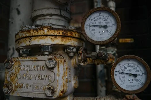
Common DAF clarifier problems include low grease removal due to failed dissolved air systems, unstable scum layers from polymer imbalance, and no air-saturated water despite working pumps. When pressure gauges show >3.5 kg but no flow, check for blocked air-saturated water releasers. A pressure difference under 0.3 kg typically indicates clogging—clean immediately to restore microbubble formation and achieve 90–95% FOG removal.
Low Grease and FOG Removal: Diagnosing Dissolved Air System Failure
Low grease removal rates, specifically those falling below the 85% efficiency threshold, are most often caused by mechanical failures within the dissolved air system rather than fluctuations in coagulant dosage (per KHN knowledge base). While operators often instinctively increase chemical feed when effluent quality drops, the root cause is frequently a lack of sufficient microbubble surface area to facilitate flotation. To diagnose this, technicians must first verify that the water recirculation pump operation and inlet water flow rate strictly match the ZSQ series DAF system for industrial wastewater design specifications, which typically range from 4 to 300 m³/h depending on the model size.
A critical diagnostic step involves monitoring the air compressor's duty cycle. If the compressor runs continuously without cycling off, it indicates a compressed air feed insufficiency or a major leak in the saturation loop. Technicians should inspect the piston rings and air valves for signs of wear or leakage, as these components are primary failure points in high-pressure air compressor systems. A common field fix is replacing the air compressor’s intake filter, which can reduce air-to-water ratio efficiency if clogged with industrial dust or humidity-related debris.
To achieve optimal microbubble dispersion, the air-to-water ratio must be maintained at a target of 0.01–0.03 m³ air/kg solids. Deviating from this range will result in either "large bubbles" that shear the floc or insufficient flotation power to lift the FOG (Fats, Oils, and Grease) particles to the surface. If the rapid fixes for mechanical screening failures upstream have already been implemented to reduce the solids load, and grease removal is still low, the problem is almost certainly an imbalance in the saturation tank pressure-to-flow ratio.
Unstable Scum Layer: Polymer and Chemical Balance Checks
Unstable or thin scum layers in a DAF clarifier commonly result from incorrect polymer dosage, degraded flocculant batches, or radical shifts in the influent TSS (Total Suspended Solids). Even a 10% deviation in polymer concentration can disrupt the floc strength, causing the scum to break apart or sink before it can be skimmed off the surface. If the polymer concentration was changed recently—perhaps during a shift change or a new chemical delivery—operators must immediately verify the concentration against the manufacturer's specification. Over-dosing is just as detrimental as under-dosing; excessive polymer can cause charge reversal, where particles begin to repel each other again, leading to a cloudy effluent and a fragile scum layer.
Influent TSS variability is a major cause of scum instability. If the influent TSS is lower than normal, the existing dosing rate will over-charge the water. Operators should recalibrate the dosing pump output using a PLC-controlled chemical dosing for DAF optimization system to ensure real-time adjustments based on influent flow and turbidity. The pH of the wastewater must be maintained within the 6.5–8.0 range. When pH falls outside this window, cationic polymers lose their effectiveness, reducing the attachment rate of microbubbles to particles. Using an online pH sensor to verify these levels is critical for maintaining consistency.
For facilities handling variable food processing waste, switching to a dual-polymer system—comprising a cationic primary polymer and an anionic booster—can provide the necessary floc stability to withstand the turbulence of the flotation zone. If the scum layer remains unstable after chemical adjustments, technicians should look at the fixing lamella clarifier performance issues protocol if the DAF is integrated with an inclined plate settler, as solids carryover from the settling stage can overwhelm the flotation stage.
No Air-Saturated Water Output Despite Pump Operation
If the water recirculation pump runs but no air-saturated water exits into the flotation tank, the technician must first confirm that the valves on the air-saturated water releasers are fully open. In many cases, these valves are manually closed during maintenance and forgotten, or they have vibrated shut over time. If the valves are open, the focus shifts to the air-saturated water releasers themselves. Scale or biofilm blockages within the releaser nozzles prevent the essential nucleation process from occurring. Without nucleation, the dissolved air remains in solution or forms large, ineffective bubbles that do not facilitate flotation.
A primary diagnostic indicator for zero-flow conditions is the pressure differential between the recirculated water line and the compressed air line. A pressure difference greater than 0.6 kg typically indicates air starvation or a massive internal leak in the saturation tank. Conversely, if the air compressor cuts out at the set pressure but no air is being injected into the water, the problem likely lies in the check valve between the compressor and the saturation tank. Sediment buildup or kinks in the compressed air piping upstream of the saturation tank can also cause this "phantom" operation where the pump is on but the process is stalled.
| Symptom | Possible Cause | Diagnostic Threshold | Required Action |
|---|---|---|---|
| Pump runs, zero flow | Releaser Blockage | Gauge >3.5 kg, No Flow | Clean/Replace Releasers |
| Continuous compressor run | Air Leak/Starvation | Diff >0.6 kg | Check Piston Rings/Leaks |
| Large bubbles only | Inlet Valve Issue | Diff <0.1 kg | Adjust Saturation Pressure |
| Low pressure, high flow | Pump Cavitation | Pressure <2.0 kg | Check Suction Line/Filter |
Reduced Air-Saturated Water Flow: Pressure Differential Diagnosis
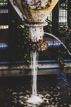
When pressure gauges on the saturation system read >3.5 kg but the flow of microbubbles into the DAF tank is visibly low, the technician should measure the pressure difference across the saturation loop. A pressure difference of less than 0.3 kg strongly suggests that the air-saturated water releasers are partially blocked (per cnwwtp.com technical support data). This blockage restricts the flow of the supersaturated liquid, preventing the "milky water" appearance that characterizes a healthy DAF system. This is a common occurrence in plants with high calcium or mineral content in their process water, which leads to rapid scale formation at the point of pressure release.
The standard repair procedure for this issue is to backflush the releasers with clean water at 5 bar for at least 5 minutes. This process should be repeated until the flow restores to the baseline levels recorded during commissioning. If backflushing fails, the releasers must be removed and soaked in a descaling solution or a weak acid bath to dissolve mineral buildup. To prevent recurrence, operators should install sight glasses on the discharge lines. These allow for a visual confirmation of microbubble generation immediately post-repair, providing an early warning sign if flow begins to diminish again.
Logging flow rates and pressure readings weekly is essential for establishing a baseline. Gradual fouling is much harder to detect than a sudden failure, but it is just as damaging to effluent compliance. If the system is also utilizing a membrane bioreactor for polishing, refer to the troubleshooting membrane bioreactor systems guide, as poor DAF performance will lead to premature membrane fouling due to grease carryover.
Preventive Maintenance Schedule for Reliable DAF Performance
DAF tanks should be drained and cleaned every 3 to 6 months depending on the FOG load; however, for high-intensity environments like meat processing or dairy plants, monthly cleaning is recommended to prevent the buildup of anaerobic sludge in the bottom of the tank. During these cleanings, the skimmer chain and bearings must be inspected for wear and lubricated quarterly to prevent mechanical binding that can trip the motor.
Calibration of pressure transmitters and flow meters should occur every 90 days. Inaccurate readings can lead an operator to make incorrect chemical adjustments, further destabilizing the system. The dissolved air efficiency should be tested annually via a microbubble count. A healthy DAF system should target 20–30 million bubbles per liter with an average bubble size of 20–50 microns. If the count is lower, it indicates that the internal components of the saturation tank or the releasers are reaching the end of their service life.
| Component | Maintenance Action | Frequency | Critical Metric |
|---|---|---|---|
| DAF Tank | Drain and Clean | 3–6 Months | No Sludge Buildup |
| Skimmer Chain | Lubricate & Tension | Quarterly | <5% Slack |
| Pressure Gauges | Calibration Check | 90 Days | +/- 0.1 kg Accuracy |
| Air Compressor | Filter Replacement | Monthly | Clean Intake |
| Microbubble Count | Efficiency Test | Annually | 20–30M Bubbles/L |
Finally, keeping a set of spare air-saturated water releasers on-site is a best practice that can reduce downtime from days to less than one hour. Because these components are the most prone to fouling, having pre-cleaned units ready for quick swaps ensures that the plant remains in compliance even during high-load events.
Frequently Asked Questions
What causes short circuiting in a clarifier?
Short circuiting is typically caused by inlet turbulence or uneven flow distribution, which allows water to bypass the treatment zone. In a DAF system, this disrupts the flotation process. Installing flow straighteners or baffles can help distribute the influent more evenly across the tank width.
What causes floating sludge in a clarifier?
Floating sludge (distinct from the intended scum layer) is often caused by denitrification gas or septic sludge buildup at the bottom of the tank. In a DAF, this can be solved by increasing the bottom rake speed or reducing the hydraulic retention time to prevent the sludge from becoming anaerobic.
How often should a DAF be drained and cleaned?
A standard DAF should be drained and cleaned every 3–6 months. However, in high-FOG environments like meat processing or industrial bakeries, monthly cleaning is necessary to prevent grease from hardening on the tank walls and internal components.
What is the difference between a clarifier and a DAF system?
Traditional clarifiers rely on gravity settling to separate solids that are heavier than water. A DAF system uses microbubbles to attach to solids and oils, floating them to the surface. This allows DAF systems to remove lighter-than-water particles like FOG much faster than a gravity clarifier.
Can pH affect DAF performance?
Yes. If the pH falls outside the 6.5–8.0 range, coagulants like ferric chloride or aluminum sulfate lose their effectiveness. This can reduce FOG removal efficiency by up to 40% as the chemical charge required for bubble attachment is neutralized.