
What the Frankfort EV/Auto Plant Is Actually Producing
An EV cell, module and pack assembly line in the Frankfort corridor discharges a wastewater fingerprint that is fundamentally different from a municipal or even a traditional stamping plant. Electrode coating, formation cycling and electrolyte handling leave residual lithium, nickel, cobalt, copper, manganese and aluminum in the process water; formation-cycle streams also concentrate fluoride and ammonia. The exact metal and fluoride concentrations vary by cell chemistry and rinse-water ratio and must be characterized at each site through grab sampling and composite sampling before specification — generic literature values for battery wastewater are not a substitute for site data.
Body, paint and final assembly lines superimpose a second pollutant class on top of the battery stream. Phosphate and zinc-rich cleaners, oils and greases from stamping and machining, paint overspray and solvents from the booth, plus surfactants from parts washers load both the organic and the metal side of biological treatment. A combined EV/auto plant must remove heavy metals, oil and grease, fluoride, ammonia, and a wide mix of solvents in a single biological stage, and the choice between MBR and CAS hinges on whether standard gravity separation is robust enough to deliver the discharge or reuse quality the KPDES permit will demand. For context on how effluent COD limits are set globally, see the 2026 global industrial COD discharge limits guide.
How MBR and CAS Differ at the Process Level
MBR and CAS share the same suspended-growth biology, where a mixed bacterial culture consumes BOD, oxidizes ammonia and, with the right aeration pattern, nitrifies and denitrifies. The split is in the solid-liquid separation step that follows: CAS uses a gravity clarifier, while MBR uses a microfiltration or ultrafiltration membrane cassette, typically submerged hollow-fibre or flat-sheet modules, or tubular sidestream modules (PCI Membranes, S4). Spiral-wound elements are not used in MBR service because of their sensitivity to suspended solids (PCI Membranes, S4).
That single substitution cascades into three downstream differences a process engineer can quantify. First, MBR retains essentially all biomass in the bioreactor, so MLSS can be pushed to levels a clarifier could not handle — and the same total mass of biomass is held in a much smaller tank. PCI Membranes reports up to 50% smaller footprint vs CAS (S4); the HydropureWater integrated MBR system (10–2,000 m³/day) is rated at 60% smaller footprint than conventional systems with <1 μm filtration (HydropureWater product catalog, S6). Second, because nothing washes out, the bioreactor hosts a more diverse microbial population with better biodegradation of recalcitrant solvents and pesticides (PCI Membranes, S4) — directly relevant to the hard-to-degrade chemicals in EV/auto lines. Third, the membrane permeate is free of suspended solids with reduced bacteria and viral content, so minimum disinfection is needed and the water can feed reverse osmosis directly (PCI Membranes, S4). A detailed walkthrough of the same contrasts in another industry segment is in the MBR cost per m³ and when to choose it (2026 guide).
MBR vs CAS for EV/Auto Wastewater: Side-by-Side Comparison
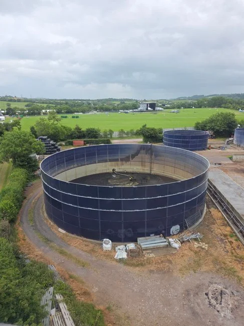
The table below consolidates the parameters a Frankfort engineer most often weighs in a pre-specification review. Numeric values are taken from the supplied research; items the research does not quantify are flagged as buyer inputs.
| Parameter | CAS | MBR | Source |
|---|---|---|---|
| Solid-liquid separation | Gravity secondary clarifier, size set by hydraulic and solids loading | MF/UF membrane cassette (hollow-fibre, flat-sheet, or tubular) | PCI Membranes, S4 |
| Footprint | Larger; circular clarifier dominates plot area | Up to 50% smaller (PCI Membranes); 60% smaller for HydropureWater integrated MBR | S4, S6 |
| Effluent suspended solids | Requires polishing and disinfection to meet tight limits | Suspended-solids-free permeate; reduced bacterial and viral content | PCI Membranes, S4 |
| Disinfection load | Full disinfection dose required | Minimum disinfection dose required | PCI Membranes, S4 |
| RO feed suitability | Needs tertiary filtration first | Permeate is RO-ready directly | PCI Membranes, S4 |
| MLSS operating range | Limited by clarifier solids loading; nitrifier washout risk on hydraulic surges | Higher MLSS sustained; no nitrifier washout | PCI Membranes, S4 |
| Recalcitrant compound biodegradation | Less diverse biomass; lower tolerance | Higher biodiversity favours degradation of solvents, pesticides, etc. | PCI Membranes, S4 |
| Hydraulic surge tolerance | Sensitive; clarifier upset risk on two-shift EV flow profiles | More tolerant; membrane tank buffers surges | PCI Membranes, S4 |
| Oil/solvent slug tolerance | More forgiving if DAF/equalization precedes the basin | Sensitive to fouling from oils, solvents and hardness; tight pretreatment envelope required | Engineering judgment, S4 |
| Membrane cassette evolution (hollow-fibre) | N/A | Second-generation PCI HF-Zmbr2 cassette: +10% packing density, −5% scouring energy vs first generation (launched 2022) | PCI Membranes, S4 |
| Pore size (submerged PVDF) | N/A | 0.02 µm (PCI HF-Zmbr2); <1 µm rating for HydropureWater integrated MBR | S4, S6 |
Two qualitative reads from the table matter most for an EV/auto project. MBR's tolerance for hydraulic surges and its complete biomass retention make it the better biological host for ammonia-bearing formation-cycle wastewater, where slow-growing nitrifiers are easily washed out of a clarifier. CAS absorbs oil and solvent slugs more gracefully as long as a DAF and equalization basin precede the aeration tank — which is why a typical retrofit keeps the existing DAF and aeration basin and slots a HydropureWater DF series flat-sheet MBR module downstream. Membrane fouling is the operating risk to plan for, and the second-generation PCI hollow-fibre cassette with −5% scouring energy and +10% packing density (S4) is a useful benchmark when comparing supplier quotes.
What Frankfort's Permits and Site Constraints Add to the Decision
Local rules compress the MBR vs CAS decision in three ways, starting with regulatory requirements. EV/auto plants discharging to a Frankfort-area POTW fall under a KPDES permit and a local pretreatment ordinance; specific numeric effluent limits for suspended solids, metals, oil and grease, fluoride and ammonia are not present in the supplied research and must be requested from the Frankfort POTW and the Kentucky Division of Water before final specification. Engineers should not assume defaults — Kentucky's limits have tightened as new battery investment has come online, and the discharge point to the Kentucky River watershed adds a receiving-water driver that municipal permits alone do not capture.
The second driver is reuse. The Frankfort corridor is co-locating new battery and EV supplier capacity alongside legacy auto assembly, and the corporate water-reuse targets that come with those programs push the specification toward an RO-ready permeate — exactly the output MBR delivers (PCI Membranes, S4; HydropureWater catalog, S6). Cooling-tower make-up, scrubber make-up, and toilet flushing are the three realistic reuse end-uses in this segment, and they all benefit from the suspended-solids-free finish. The third driver is plot area. Existing auto assembly sites are space-constrained; MBR's rectangular membrane-tank geometry replaces a large circular clarifier and frees up production floor area (PCI Membranes, S4; HydropureWater catalog, S6). The parameter checklist a buyer should request from each supplier in this region is summarized below.
| Local constraint | Why it matters in Frankfort | Buyer input required |
|---|---|---|
| KPDES permit limits | Sets numeric effluent targets for SS, metals, oil & grease, fluoride, ammonia | Current KPDES permit text and POTW pretreatment limits |
| Discharge to Kentucky River | Receiving-water quality adds a watershed driver beyond the POTW permit | Watershed-specific TMDL and receiving-water data from Kentucky Division of Water |
| On-site reuse target | Drives RO-feed specification and overall MBR vs CAS choice | Corporate reuse % and target end-uses (cooling tower, scrubber, toilet flushing) |
| Plot area | Constrained on existing assembly sites; favors compact MBR geometry | Available footprint for biological and clarification stages |
| Hydraulic profile | Two-shift EV lines produce high daytime, near-empty night flow | Daily flow duration curve and peak-to-average ratio |
A second comparison anchor for an adjacent industrial segment — petroleum and coal — is in the MBR vs CAS for petroleum and coal wastewater in Atlanta guide; the hydraulic-surge and oil-tolerance logic is similar even though the pollutant fingerprint differs.
Decision Framework: When to Choose MBR or Stay With CAS in Frankfort
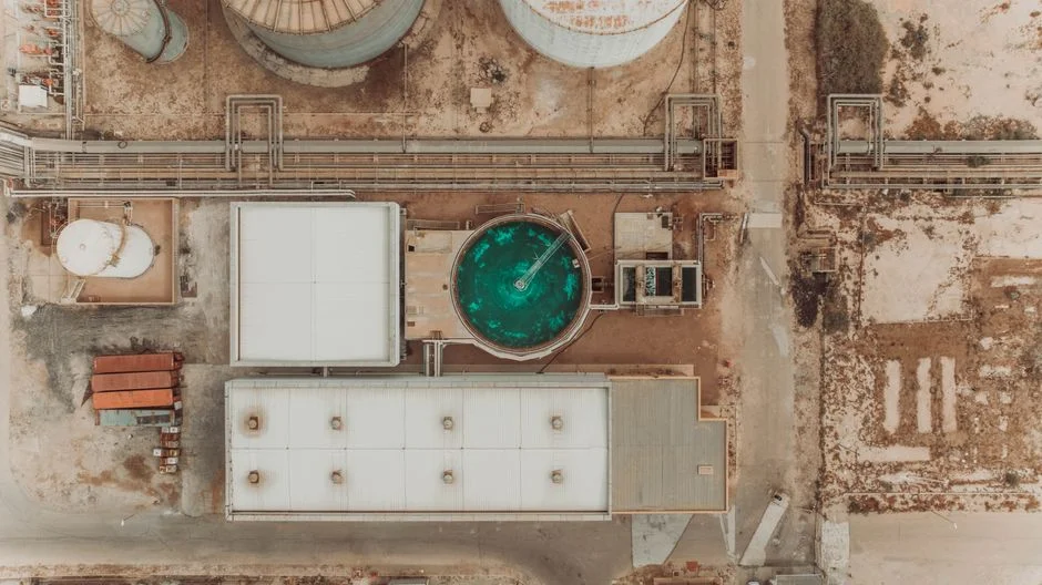
Translate the comparison into a specification by working through four questions regarding KPDES limits, reuse goals, plot constraints, and flow profiles. If the answers lean toward tight limits, reuse, constrained space, and variable flow, the project is an MBR project; the 50–60% footprint advantage (S4, S6) and the RO-ready permeate (S4) directly address the three binding constraints. If the answers lean toward conventional, available, and steady conditions, CAS remains the lower-capex option and a HydropureWater DAF unit as MBR pretreatment ahead of the aeration basin is usually enough to keep the basin healthy.
For a Frankfort retrofit where the aeration basin is already paid for and only the secondary separation is undersized, a hybrid path is often the cheapest answer: keep the existing CAS biology, add an MBR cassette downstream, and shrink or repurpose the clarifier. That option should be on the table in any project meeting where the capital review asks whether to spend on new biology or on a separation upgrade.
Frequently Asked Questions
How should a Frankfort engineer size an MBR vs a CAS system for an EV/auto plant?
Size both systems on the same influent BOD, COD, ammonia and flow data from a site-specific sampling campaign — generic wastewater values are not a substitute. For MBR, the binding constraints are membrane area, peak flux, and target MLSS, with the HydropureWater integrated MBR system (10–2,000 m³/day) range covering most single-line auto and battery lines. For CAS, the binding constraints are clarifier hydraulic and solids loading; PCI Membranes (S4) shows why that geometry consumes the larger plot area.
What budget line items should a Frankfort engineer request from MBR and CAS suppliers?
Request a lifecycle cost split on membrane replacement, scour-air energy, chemical cleaning, and sludge handling — not just a turnkey capex number. The second-generation PCI hollow-fibre cassette reports −5% scouring energy and +10% packing density vs the first generation (PCI Membranes, S4); ask each bidder for the same generation benchmark and the same metric split so quotes are comparable.
What KPDES and pretreatment information should be on hand before specifying MBR vs CAS?
Before final specification, the engineer must request the current KPDES permit text, the local POTW pretreatment ordinance, and any watershed-specific requirements from the Kentucky Division of Water. Numeric limits for suspended solids, metals, fluoride, ammonia, and oil & grease are not in the supplied research and must be confirmed with the regulator; assuming defaults risks re-permitting later.
What supplier selection checks matter most for a Frankfort MBR retrofit?
Verify that the supplier offers both submerged and sidestream membrane geometries, can supply cassettes with documented packing-density and scouring-energy gains (PCI Membranes, S4 documents the +10% / −5% benchmark), and has a regional service footprint for membrane replacement and CIP chemistry. A pilot test on the actual EV/auto wastewater is the strongest single check before committing capex.