Why Wafer Fab Developer Wastewater Defies Conventional Treatment
A single wafer fab generates 2–4 million gallons of developer wastewater daily, loaded with sub-300 nm colloidal silica, metal oxides, and photoresist residues that resist conventional filtration. Hybrid systems combining dissolved air flotation (DAF), membrane bioreactors (MBR), and reverse osmosis (RO) achieve 99.8% TSS removal and enable zero liquid discharge (ZLD), but CAPEX ranges from $1.2M–$5M depending on fab size and recovery targets. This guide provides 2025 engineering specs, cost breakdowns, and a step-by-step design framework for semiconductor fabs.
Developer wastewater is a complex stream primarily composed of tetramethylammonium hydroxide (TMAH), photoresist residues (typically 1–5% w/w), and engineered nanoparticles like colloidal silica. These particles are intentionally designed with high stability to prevent aggregation during the lithography process. This stability is the primary reason conventional gravity clarifiers fail; the sub-300 nm particles possess a high negative surface charge, resulting in a zeta potential of -30 to -50 mV (cite ASTM D4189-16 for silica stability). Without precise chemical destabilization, these particles remain in suspension indefinitely.
Influent Total Suspended Solids (TSS) in developer streams typically range from 500–3,000 mg/L, while Chemical Oxygen Demand (COD) can spike to 10,000 mg/L depending on the photoresist chemistry and stripping frequency (per EPA 2024 semiconductor wastewater benchmarks). Standard media filters are ineffective because the colloidal silica bypasses the pore spaces and fouls downstream membranes within hours. A case study from a 300 mm fab in Taiwan documented a membrane flux drop from 25 LMH to 5 LMH in just 48 hours due to unoptimized pretreatment (source: IEEE Transactions on Semiconductor Manufacturing, 2023). To overcome this, the coagulation process requires 3–5x more coagulant than municipal applications to overcome the electrostatic repulsion of the colloids.
| Parameter | Developer Wastewater Characteristic | Operational Challenge |
|---|---|---|
| Particle Size | 50–300 nm (Colloidal Silica) | Bypasses sand/multi-media filters; causes rapid pore plugging. |
| Zeta Potential | -30 to -50 mV | High electrostatic repulsion; requires massive coagulant dosing. |
| TMAH Concentration | 500–2,500 mg/L | Inhibits biological nitrification; toxic to standard activated sludge. |
| Photoresist Residue | 1–5% w/w | High COD and foaming potential in aeration tanks. |
2025 Engineering Specs for Developer Wastewater: Influent, Effluent, and Treatment Targets
Designing an effective treatment train requires precise benchmarking of influent loads against stringent regulatory and reuse targets. While local discharge limits vary, the global trend is moving toward Zero Liquid Discharge (ZLD) or high-purity reuse to mitigate water scarcity risks in semiconductor manufacturing hubs. Effluent targets for direct discharge generally require TSS <5 mg/L, whereas reuse for ultrapure water (UPW) makeup requires TSS <1 mg/L and significantly lower TOC levels.
TMAH management is a critical engineering hurdle. As a quaternary ammonium compound, TMAH is biodegradable but inhibits nitrifying bacteria at concentrations exceeding 50 mg/L (cite Water Research, 2022). Consequently, systems must be designed with adequate equalization and potentially a two-stage biological approach to ensure complete degradation before discharge. regulatory frameworks such as China’s GB 31573-2015 mandate TMAH levels below 1 mg/L, while the US EPA 40 CFR Part 469 sets strict limits on associated metals like Copper (<1.3 mg/L) and Nickel (<2.38 mg/L). For fabs pursuing ZLD, the system must be capable of handling Total Dissolved Solids (TDS) exceeding 50,000 mg/L in the final brine streams before evaporation.
| Parameter | Typical Influent | Discharge Limit (GB/EPA) | Reuse Target (UPW/Scrubber) |
|---|---|---|---|
| TSS (mg/L) | 500 – 3,000 | < 10 – 30 | < 1.0 |
| COD (mg/L) | 2,000 – 10,000 | < 50 – 100 | < 10 |
| TMAH (mg/L) | 500 – 2,500 | < 1.0 | < 0.1 |
| Total Silica (mg/L) | 200 – 800 | < 50 | < 5 |
| Copper (mg/L) | 5 – 50 | < 0.5 – 1.3 | < 0.05 |
| pH | 11.0 – 13.0 | 6.0 – 9.0 | 7.0 – 8.0 |
To meet these specifications, engineers often utilize a submerged MBR system for colloidal silica and TMAH removal, which provides the high-quality permeate necessary for downstream reverse osmosis. This is often integrated with CMP wastewater treatment solutions for semiconductor fabs to streamline the overall facility water balance.
Hybrid System Design: Step-by-Step Process Flow for 99.8% TSS Removal
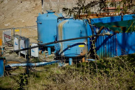
The most resilient design for developer wastewater is a multi-stage hybrid system that sequences physical-chemical separation, biological degradation, and membrane desalination. This approach ensures that the most difficult-to-treat components—colloidal silica and TMAH—are addressed by the specific technologies best suited for their removal.
Step 1: Pretreatment with DAF. The primary goal is the removal of bulk TSS and photoresist residues. A high-efficiency DAF system for semiconductor wastewater pretreatment is utilized here. Key parameters include an air-to-solids ratio of 0.02–0.04 and a hydraulic loading rate of 4–6 m³/m²·h. Chemical conditioning is vital: Polyaluminum Chloride (PAC) is typically dosed at 50–150 mg/L to destabilize the silica, followed by an anionic polymer at 1–3 mg/L to form buoyant flocs.
Step 2: MBR with Flat-Sheet Membranes. The DAF effluent flows into an equalization tank and then into the MBR. This stage targets TMAH biodegradation and provides <1 μm filtration. Engineering specs for this stage include a flux rate of 15–25 LMH and Mixed Liquor Suspended Solids (MLSS) maintained between 8,000–12,000 mg/L. Aeration rates should be set at 0.2–0.4 m³/m²·h to support both biological activity and membrane scouring.
Step 3: RO for TDS and Organic Removal. Permeate from the MBR is processed by a high-recovery RO system for semiconductor wastewater reuse. This stage removes residual dissolved salts and organic traces, typically achieving 70–85% water recovery. Operating pressures range from 15–30 bar, with antiscalant (phosphonates) dosed at 2–5 mg/L to prevent silica scaling on the membrane surface.
Step 4: Evaporation/Crystallization for ZLD. For fabs requiring ZLD, the RO brine (TDS >50,000 mg/L) is sent to a Mechanical Vapor Recompression (MVR) evaporator. This stage is energy-intensive, consuming 20–40 kWh/m³, but it eliminates liquid discharge entirely. A common pitfall in this sequence is RO fouling from residual silica. To mitigate this, some designs incorporate a second DAF stage or ceramic ultrafiltration before the RO to ensure the SDI (Silt Density Index) remains below 3.0.
| Treatment Stage | Equipment Selection | Key Design Parameter |
|---|---|---|
| Bulk TSS Removal | DAF (Dissolved Air Flotation) | PAC Dose: 100 mg/L; Air/Solids: 0.03 |
| Biological/Fine TSS | MBR (Membrane Bioreactor) | Flux: 20 LMH; HRT: 18-24 Hours |
| Desalination | RO (Reverse Osmosis) | Recovery: 75%; Pressure: 20 bar |
| Brine Management | MVR Evaporator | Energy: 30 kWh/m³; Feed TDS: >5% |
Cost Breakdown: ZLD vs. Partial Reuse for Developer Wastewater
Justifying the budget for a developer wastewater system requires a clear comparison between the CAPEX-heavy ZLD approach and the OPEX-focused partial reuse model. While ZLD eliminates discharge fees and environmental compliance risks, the capital investment for evaporation equipment can double the total project cost. For a standard 100 m³/h treatment system, the evaporator alone can represent 50% of the CAPEX.
Operating expenses (OPEX) are driven by energy for evaporation and chemical consumption for pretreatment. In a partial reuse scenario (80% recovery), the OPEX typically ranges from $0.80 to $1.20/m³. In contrast, ZLD OPEX can climb to $2.50/m³ due to the high energy demand of thermal crystallization. However, the ROI for these systems is often found in the avoidance of freshwater purchase costs (averaging $5/m³ in some semi-arid fab regions) and the mitigation of "hidden" costs like sludge disposal, which can range from $150–$300/ton for hazardous semiconductor waste.
| Component (100 m³/h System) | Partial Reuse (80%) CAPEX | ZLD (100%) CAPEX |
|---|---|---|
| Pretreatment (DAF + Chem) | $200,000 | $200,000 |
| Biological (MBR) | $500,000 | $500,000 |
| Membrane (RO) | $300,000 | $450,000 (High Pressure) |
| Thermal (MVR/Crystallizer) | $0 | $1,200,000 |
| Total Estimated CAPEX | $1,000,000 | $2,350,000 |
The payback period is calculated as: Payback = (CAPEX) / (Annual Water Savings + Avoided Discharge Fees). For a 200 m³/h system, a fab can save approximately $1.5M annually in water costs and avoid $200K in regulatory fees, often leading to a payback of less than 2 years for reuse systems. For more detail, refer to our detailed cost breakdowns for semiconductor wastewater ZLD systems, which includes an interactive ROI calculator for EHS managers.
Troubleshooting Developer Wastewater Treatment: 5 Common Failures and Fixes
Even with advanced hybrid designs, the unique chemistry of developer wastewater can lead to operational disruptions. Rapid diagnosis is essential to prevent fab downtime.
- Failure 1: DAF effluent TSS >50 mg/L.
Cause: Insufficient coagulant dose or air-to-solids ratio mismatch.
Fix: Perform a jar test to optimize PAC/polymer dose. Target a zeta potential of -10 to +5 mV to ensure complete destabilization of colloidal silica. - Failure 2: MBR membrane fouling (flux <10 LMH).
Cause: Residual silica or organic photoresist fouling on the membrane surface.
Fix: Implement an intensive chemical cleaning (CIP) cycle using 0.5% NaOH + 0.2% NaOCl with a 2-hour soak to dissolve organic residues. - Failure 3: RO permeate COD >20 mg/L.
Cause: Organic breakthrough from the MBR, often due to high-molecular-weight photoresist fragments.
Fix: Install a Granular Activated Carbon (GAC) filter or an ozone oxidation step between the MBR and RO to polish residual organics. - Failure 4: Evaporator scaling.
Cause: Excessive silica or calcium in the brine stream exceeding solubility limits.
Fix: Increase antiscalant dosing (specifically phosphonates) or introduce an ion-exchange softening step for the RO brine before it enters the evaporator. - Failure 5: TMAH carryover into effluent.
Cause: Incomplete biodegradation in the MBR due to low Hydraulic Retention Time (HRT) or toxic shock.
Fix: Increase HRT to 24+ hours or add Powdered Activated Carbon (PAC) directly to the MBR to provide additional surface area for specialized bacteria.
For more complex ZLD configurations, engineers should review ZLD system designs for GaN/SiC wastewater to understand how different semiconductor substrates impact troubleshooting protocols.
Frequently Asked Questions
Q: What’s the best pretreatment for developer wastewater before MBR?
A: Dissolved air flotation (DAF) is superior to settling because photoresist and silica flocs are often light and buoyant. Dosing PAC at 100–150 mg/L and anionic polymer at 1–3 mg/L typically removes 90–95% of TSS, significantly protecting the downstream MBR from fouling (per IEEE 2024 benchmarks).
Q: Can developer wastewater be reused for UPW production?
A: Yes, but it requires a "polishing" train. After the hybrid DAF-MBR-RO process, the water must pass through Electrodeionization (EDI) or mixed-bed ion exchange to achieve <1 ppb TOC and <0.1 μS/cm conductivity. Most fabs currently reuse 70–85% for non-critical applications like cooling towers first.
Q: What’s the CAPEX for a 50 m³/h ZLD system for developer wastewater?
A: A 50 m³/h ZLD system typically costs between $2.5M and $4M. This includes the DAF pretreatment, MBR biological stage, RO desalination, and the thermal evaporator. OPEX for such a system ranges from $0.80 to $1.50/m³ depending on local energy costs.
Q: How do you handle TMAH in developer wastewater?
A: TMAH is biodegradable but can be toxic to nitrifying bacteria in high concentrations. The most robust method is a two-stage MBR where the first stage is optimized for TMAH degradation and the second for nitrification. For concentrations >100 mg/L, chemical oxidation like Fenton’s reagent may be required as a pretreatment.
Q: What are the discharge limits for developer wastewater in China vs. the US?
A: China (GB 31573-2015) is often stricter regarding TMAH (<1 mg/L) and specific metals like Nickel (<1 mg/L). The US (EPA 40 CFR Part 469) focuses heavily on Copper (<1.3 mg/L) and Nickel (<2.38 mg/L). Both regions generally require a pH between 6.0 and 9.0.