لماذا يتعطل المقارنة المعيارية بين DAF والمروّق عند تطبيقها على مياه صرف أشباه الموصلات
إن المقارنات العامة بين DAF والمروّق المبنية على معالجة الأغذية أو الشحوم والدهون والزيوت تُقلّل من حجم المشكلة التي يواجهها مهندسو مصانع التصنيع في ساوث هادلي: إذ يحمل تيار المعالجة المسبقة النموذجي في المصنع جسيمات كولويدية من السيليكا بحجم دون 10 µm، وبقايا ملاط CMP (التسطيح الكيميائي-الميكانيكي) من السيريا والألومينا، ومحاليل الشطف الحامضية/التعرية المحتوية على الفلوريد، ومُفرّغات غسّال الفلوريد، ومخلفات كاشف المقاوم الضوئي TMAH (هيدروكسيد رباعي ميثيل الأمونيوم)/IPA (كحول الأيزوبروبيل). إن هذه الكيميائيات الأربع تُحرّك كل عملية وحدة في اتجاه التيار بعد المروّق الأولي، وهي تتشارك خاصية واحدة — ألا وهي أن الجسيمات المستهدفة لا تترسب بالجاذبية في أي زمن احتجاز عملي. فالسيليكا الكولويدية والمواد الكاشطة النانوية ذات كثافة شبه محايدة، وأقطار جسيماتها دون 10 µm، ولها شحنات سطحية تُبقيها في حالة تعليق مستقر؛ وهي الهدف الكلاسيكي للتعويم لا للترسيب.
تستخدم هذه المقالة نظام التعويم بالهواء المذاب من HydropureWater (4–300 m³/h، 13 موديلاً، تحميل هيدروليكي 4–25 m/h) والمروّق الصفيحي من HydropureWater (تحميل سطحي 20–40 m/h، استهلاك كيميائي أقل بنحو 30% مقارنة بالمُروقات التقليدية) كخطوط أساس للمقارنة. يعمل المروّق التقليدي عند 1–3 m/h؛ والمروّق الصفيحي عند 20–40 m/h؛ وDAF عند 4–25 m/h. هذه الأرقام غير قابلة للتبادل، وبما أن المساحة المتاحة في طابق المصنع محدودة، فإن معدل التحميل وحده يُحرّك القرار قبل النظر في الكيمياء.
DAF مقابل المروّق الصفيحي: مصفوفة المعايير وجهاً لوجه
تُقيّم الجدول التالي كلتا التقنيتين وفق المعايير العشرة التي تُحرّك قرار المعالجة المسبقة في المصنع. تتناسب أرقام المساحة مع تدفق تصميمي قدره 50 m³/h؛ وتعكس نطاقات CAPEX/OPEX حدود الميزانية لعام 2026 للإنشاءات الصناعية من الفولاذ المقاوم للصدأ/FRP في شمال شرق الولايات المتحدة.
| المعيار | DAF | المروّق الصفيحي | الفائز في خدمة المصنع |
|---|---|---|---|
| معدل التحميل الهيدروليكي | 4–25 m/h | 20–40 m/h | الصفيحي (معدل)؛ DAF (التقاط الجسيمات) |
| المساحة لكل m³/h (خط 50 m³/h) | ~2–4 m² لكل m³/h | ~1.5–3 m² لكل m³/h | الصفيحي |
| الإزالة النموذجية للمواد الصلبة العالقة الكلية | 85–95% مع PAC (كلوريد البولي ألومنيوم)/بوليمر | 60–80% للكولويدات؛ 70–90% للتكتلات الأكبر | DAF |
| حجم الجسيمات المستهدف | 2–50 µm (مثالي دون 10 µm) | أكثر من 20 µm، ويفضل أكثر من 50 µm | DAF |
| إزالة الشحوم والدهون وTMAH | قوية (تُعوّم الزيوت والتكتلات منخفضة الكثافة) | متوسطة (تعتمد على الكشط السطحي) | DAF |
| معالجة الترسبات المشتركة للفلوريد والمعادن | ممتازة لتكتل CaF₂ منخفض الكثافة | ضعيفة — التكتل الخفيف يتجاوز الهدّارات | DAF |
| المواد الصلبة الجافة في الحمأة | 3–6% DS (أكثر تماسكاً، محتوى مائي أقل) | 1–2% DS (محتوى مائي مرتفع) | DAF |
| الاستهلاك الكيميائي | خط أساس PAC + بوليمر أنيوني | أقل بنحو 30% (هندسة صفيحية) | الصفيحي |
| نطاق CAPEX (20–50 m³/h) | $80K–$250K | $60K–$180K | الصفيحي (أرخص مقدماً) |
| المُميّز في OPEX | ضاغط هواء + مضخة مُشبّع؛ حمأة أكثر تماسكاً تُقلل النقل | طاقة أقل؛ حمأة أخف ترفع تكلفة التخلص | DAF (على المدى الطويل) |
إن الفوائد التشغيلية لـ DAF يدعمها دراسة سابقة على الغشاء قبل DAF من ASABE لعام 2012: حيث تمت معالجة مياه صرف تصنيع الدواجن الخام بنقطة كيميائية 5263 mg/L COD (الأكسجين الكيميائي المطلوب) و3355 mg/L TS (المواد الصلبة الكلية) بنجاح من خلال غربال أولي ثم ترشيحها عند 115 L/m²/h عبر غشاء PVDF (فلوريد البولي فينيلدين) بمسامية 0.3 µm. وعند إسقاط هذا التدفق وحمولة الجسيمات على قطار تلميع RO/التبادل الأيوني في المصنع، تتضح حجة DAF كحارس أعلى القطار لأغشية مياه فائقة النقاء (UPW): إذ إن DAF المُصمّم جيداً يُخفض المواد الصلبة العالقة الكلية والحمل الكوليدي قبل وصول الماء إلى رف RO.
كثيراً ما يُغفل المهندسون حلقة إعادة تدوير الماء المُشبّع بالهواء في DAF، والتي تضيف مضخة ماء مُشبّع وضاغط هواء (عادةً 5–15 kW على وحدة 50 m³/h) لكنها موفّرة للطاقة مقارنة بآلية الكشط السطحي الكاملة للمروّق. وعلى جدول تشغيل 16 ساعة/يوم، يؤثر هذا الفرق في بند استهلاك kWh وتكلفة نقل الحمأة.
ثلاثة سيناريوهات لمصانع ساوث هادلي: أي وحدة تفوز
توضح السيناريوهات التالية كيفية تطبيق مصفوفة التكنولوجيا على تيارات محددة في المصنع، باستخدام تقديرات ميزانية عام 2026 للإنشاءات الصناعية من الفولاذ المقاوم للصدأ/FRP.
| السيناريو | كيمياء التيار | المعالجة الأولية الموصى بها | السبب |
|---|---|---|---|
| ملاط CMP + شطف ما بعد CMP | مواد نانوية كاشطة SiO₂، CeO₂، Al₂O₃، دون 10 µm | DAF + جرعات المُخثر | الجسيمات دون 10 µm؛ والتخثير (50–150 mg/L PAC + 1–3 mg/L بوليمر أنيوني) يُلصقها بالفقاعات الدقيقة؛ وتحميل DAF البالغ 4–25 m/h يتفوق على احتجاز 4–6 ساعة الذي يحتاجه المروّق لالتقاط مماثل. |
| مزيج الأحماض/التعرية + مُفرّغ غسّال الفلوريد | HF، NH₄F، SiO₂، معادن مذابة | ترسيب Ca²⁺ ← DAF كمعالجة أولية | إضافة CaCl₂ أو Ca(OH)₂ للوصول إلى pH 8–9.5 تُحرّك الترسيب المشترك لـ CaF₂ + هيدروكسيد المعادن؛ وتكتل الفلوريد منخفض الكثافة الناتج يتجاوز هدّارات المروّق لكنه يطفو بنظافة في DAF. |
| مخلفات كاشف TMAH/IPA | pH مرتفع، TSS منخفض، مواد صلبة لمقاوم ضوئي | مروّق صفيحي كموازن ← DAF في اتجاه التيار | TMAH يتحلل بيولوجياً ببطء؛ الأولوية هي التقاط المواد الصلبة العالقة وتخفيف الحمل على الخطوة البيولوجية. DAF في اتجاه التيار يُزيل الهواء المحمول من فيض الناشر، مما يحمي الوحدات البيولوجية التالية. |
كلما كانت مجموعة الجسيمات أصعب في الترسيب، ازداد استحقاق DAF لمكانه. ويظل المروّق الصفيحي مفيداً كموازن أو خطوة تلميع، لكنه في عام 2026 نادراً ما يكون المعالجة الأولية الصحيحة لتيار في المصنع. إذا كان مصنعكم يمزج الأنواع الثلاثة من المخلفات في خط رئيسي مشترك، فإن التوصية هي معالجة مُرتّبة: معادلة، وتعديل pH والكالسيوم، وجرعات المُخثر/البوليمر، وDAF كخطوة إزالة أولية للمواد الصلبة، ثم ترشيح مزدوج الوسائط قبل قطار تلميع RO/IX (التبادل الأيوني).
الامتثال في عام 2026: حدود ماساتشوستس وEPA التي تُحرّك الاختيار
لا يُلبّي DAF ولا المروّق حدود التصريف بمفرده. يتركز الاخيار بينهما على أي مروّق أولي يحمي قطار التلميع بمزيد من الموثوقية، بما يضمن أن تعديل pH في اتجاه التيار، والترسيب الكيميائي، وعمل الأغشية تستوفي المتطلبات التنظيمية. بالنسبة لمصنع يُصرّف إلى POTW (محطة معالجة مياه صرف مملوكة للقطاع العام) في ماساتشوستس عام 2026، فإن الأرقام الملزمة هي معايير المعالجة المسبقة التصنيفية لتشطيب المعادن EPA في 40 CFR Part 433 — حدود يومية قصوى Cu 4.1 mg/L، وNi 4.1 mg/L، وCr 7.0 mg/L، وZn 10.5 mg/L، وPb 1.6 mg/L، وCd 1.2 mg/L، والسيانيد الكلي 5.0 mg/L. هذه معايير تصنيفية للمعالجة المسبقة وليست إرشادات، وتنطبق على كل مُصرّف في قطاع تشطيب المعادن أو الإلكترونيات في البلاد.
على الجانب الخاص بماساتشوستس، يُحدد 314 CMR 7.00 إطار مياه الصرف الصناعي، وتكمل الحدود المحلية لمحطات POTW بقية المتطلبات. وفي منطقة خدمة ساوث هادلي/هوليوك، تتراوح حدود المجاري المحلية النموذجية للفلوريد بين 10–50 mg/L، ويخضع TMAH للتنظيم على أساس COD (غالباً <100 mg/L COD)، وتُفرض متابعة المعادن الكلية من خلال 40 CFR 433. ويتطلب الوصول إلى هذه الأرقام من تيار مصنع يحتوي على سيليكا كولويدية وفلوريد جرعة مُخثر، وتعديل pH إلى نحو 8–9.5 لترسيب الفلوريد، ومروّقاً أولياً يلتقط التكتل الناتج دون إرساله فوق الهدّار.
يُزيل DAF مجموعة الجسيمات التي كانت ستُسبب تلوث الترسيب الكيميائي وRO/IX في اتجاه التيار، داخل مساحة صغيرة في المصنع. وفيما تظل أرقام 40 CFR 433 وإطار 314 CMR 7.00 ثابتة، فإن هامش الامتثال الهندسي يتحسن مع اختيار المروّق الصحيح.
التكلفة، والمساحة، والتكامل مع قطار تلميع مياه فائقة النقاء (UPW)
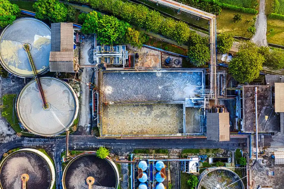
لميزانية عام 2026، يقع هيكل DAF المُعدّل لخط معالجة مسبقة في المصنع بسعة 20–50 m³/h في النطاق $80K–$250K؛ أما المروّق الصفيحي المُكافئ فيتراوح بين $60K–$180K. تغطي هذه النطاقات الإنشاءات الصناعية من الفولاذ المقاوم للصدأ وFRP (البلاستيك المقوى بالألياف الزجاجية) مع لوحات تحكم PLC (وحدة تحكم منطقية قابلة للبرمجة)، وهي ميزانية وليست عروض EPC (الهندسة والمشتريات والبناء) تسليم المفتاح؛ فالأنابيب والأعمال المدنية ووحدات الجرعات الكيميائية إضافية. وبند OPEX (النفقات التشغيلية) هو حيث يسترد DAF علامته premium: فحمأة DAF بنسبة 3–6% مواد صلبة جافة تُقلل دورات مكبس الترشيح في اتجاه التيار وأطنان نقل الحمأة، في حين أن حمأة المروّق الصفيحي عادةً ما تكون 1–2% مواد صلبة جافة. لخط 50 m³/h يعمل 16 ساعة/يوم، يُعدّ هذا الفرق جوهرياً في تكاليف التخلص السنوية من الحمأة.
التكامل مُباشر. تتغذى المياه الخارجة من DAF عادةً على قطار ترشيح من مرحلتين — مرشح متعدد الوسائط لتلميع TSS يليه كربون منشط للمواد العضوية الأثرية — ثم نظام التناضح العكسي بالإضافة إلى التبادل الأيوني لمياه تعويضة فائقة النقاء (UPW). تنخفض حمأة DAF من المُكثّف إلى مكبس ترشيح ألواح وإطارات لتجفيفها حتى تصل إلى كيك بنسبة 25–35% مواد صلبة جافة قبل التخلص خارج الموقع. في المقابل، تحتاج المياه الخارجة من المروّق عادةً إلى جرعة مُخثر أضيق بالإضافة إلى تلميع DAF قبل أن تصبح نظيفة بما يكفي لـ RO. وفي مصنع تصل فيه تكلفة استبدال أغشية RO إلى ستة أرقام لكل رف، فإن الحماية التي يوفرها DAF في اتجاه التيار تُعدّ تأميناً فعّالاً من حيث التكلفة.
الأسئلة الشائعة
بالنسبة لمصنع أشباه الموصلات في ساوث هادلي، هل DAF أفضل من المروّق في عام 2026؟
يُعد DAF الخيار الأفضل افتراضياً للترويق الأولي في المصنع لأن السيليكا الكولويدية، وبقايا ملاط CMP، والترسبات المشتركة للفلوريد والمعادن كلها جسيمات دون 10 µm وتطفو بنظافة على الفقاعات الدقيقة. ويُفضّل المروّق الصفيحي فقط كخطوة تلميع أو معادلة قبل DAF أو وحدة بيولوجية في اتجاه التيار. لمزيد من السياق حول عمليات المصنع، يُرجى الاطلاع على دليل امتثال مياه صرف عمليات أشباه الموصلات وقاعات البيانات.
ما نسبة إزالة TSS التي يمكن أن يحققها DAF على مياه صرف المصنع؟
مع الجرعات الصحيحة من المُخثر والبوليمر (عادةً 50–150 mg/L PAC بالإضافة إلى 1–3 mg/L بوليمر أنيوني)، يصل DAF بانتظام إلى إزالة TSS بنسبة 85–95% على التيارات الصناعية. وأظهرت بيانات مستقلة قبل DAF من ASABE لعام 2012 خفض 3355 mg/L TS الخام مادياً عبر غشاء PVDF بمسامية 0.3 µm عند 115 L/m²/h، مما يؤكد خفض الحمل الذي يُسلّمه DAF إلى قطار UF/RO (الترشيح الفائق/التناضح العكسي) في اتجاه التيار.